Eureka AIR delivers breakthrough ideas for toughest innovation challenges, trusted by R&D personnel around the world.

Optical device and display equipment

An optical device and grating technology, applied in the field of waveguide, to achieve the effect of good color uniformity, improved utilization and large FOV

Pending Publication Date: 2021-08-06
SHENZHEN OPTIARK SEMICON TECH LTD
View PDF0 Cites 8 Cited by
  • Summary
  • Abstract
  • Description
  • Claims
  • Application Information

AI Technical Summary

Problems solved by technology

[0004] This application provides an optical device and a display device to solve the problem that the current optical waveguide can only realize monocular display

Method used


Image

  • Optical device and display equipment
  • Optical device and display equipment
  • Optical device and display equipment

Examples


Embodiment Construction

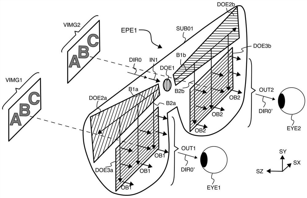
[0025] The following will clearly and completely describe the technical solutions in the embodiments of the present disclosure with reference to the accompanying drawings in the embodiments of the present disclosure. Apparently, the described embodiments are part of the embodiments of the present disclosure, not all of them. Based on the embodiments in the present disclosure, all other embodiments obtained by those skilled in the art without making creative efforts belong to the protection scope of the present disclosure.

[0026] Specific embodiments of the present disclosure will be described in detail below in conjunction with the accompanying drawings.

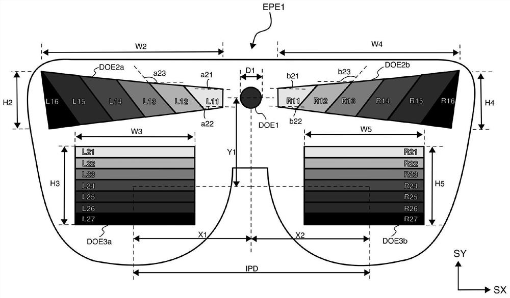
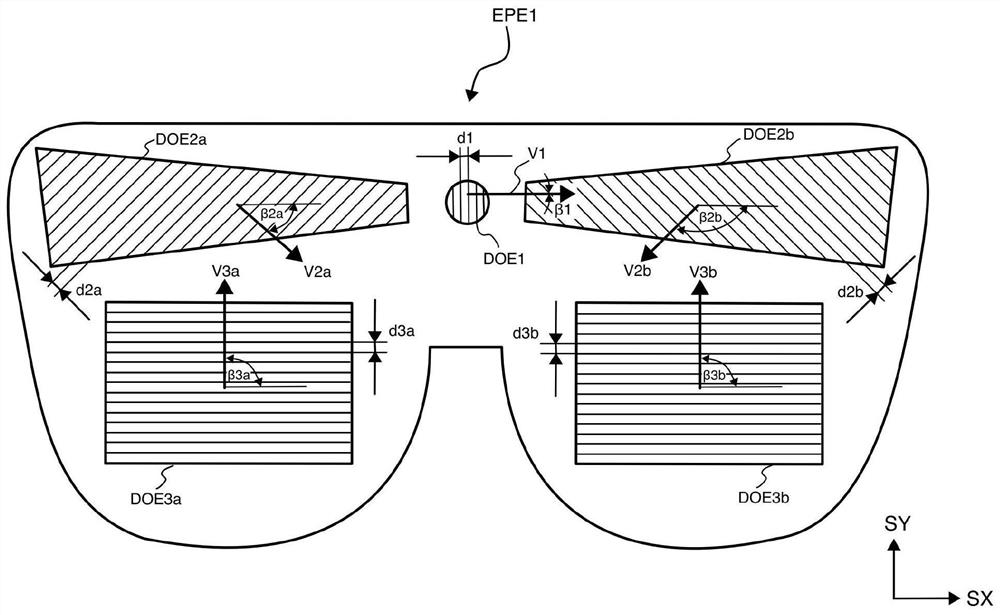
[0027] Such as figure 1 As shown, the optical device EPE1 may include a waveguide plate SUB01, which is a plane with good flatness, but the shape of the waveguide plate SUB01 can be a flat plate, or a bent plate that fits a human face, all of which have good flatness .

[0028] An entrance pupil grating unit DOE1, a left...


PUM

PropertyMeasurementUnit
Diameteraaaaaaaaaa

Abstract

The invention relates to an optical device and display equipment, the optical device comprises a waveguide plate, an entrance pupil grating unit, a left pupil expanding grating unit located on the left side of the entrance pupil grating unit and a right pupil expanding grating unit located on the right side of the entrance pupil grating unit are formed on the waveguide plate, and the left pupil expanding grating unit and the right pupil expanding grating unit are in left-right mirror symmetry with the entrance pupil grating unit as the center; the left and right exit pupil grating units are positioned below the left and right pupil expanding grating units and are also arranged in a left and right mirror symmetry manner; input light is diffracted by the entrance pupil grating unit to form first left conduction light and first right conduction light, the first left conduction light is diffracted by the left pupil expanding grating unit to form second left conduction light, and the first right conduction light is diffracted by the right pupil expanding grating unit to form second right conduction light; the second left conduction light is diffracted into left output light through the left exit pupil grating unit; the second right conduction light is diffracted into right output light through a right exit pupil grating unit; and the input light, the left output light and the right output light are consistent in direction. Binocular display can be realized through the waveguide, and the color uniformity can be improved.

Description

technical field [0001] The application belongs to the field of waveguide technology, and in particular relates to an optical device and a display device. Background technique [0002] Near-eye display technology is one of the key technologies that must be used in current AR glasses. The near-eye display system is generally composed of an image remote and an optical transmission system. The image frame emitted by the image source is transmitted to the human eye through the optical transmission system. The optical transmission system here needs to have a certain transmittance, so that the wearer can see the external environment while seeing the image. [0003] For the optical transmission system, there are many solutions in the industry, for example, free-space optics, free-form surface optics, and display optical waveguides. Among them, optical waveguide technology has become the mainstream path of major companies due to its large eyebox characteristics and its light and th...

Claims


Application Information

Patent Timeline
IPC IPC(8): G02B27/01G02B27/00G02B6/10G02B5/18
CPCG02B27/0172G02B27/0081G02B6/10G02B5/1819G02B2027/0132G02B2027/0123G02B2027/0178G02B27/4272G02B27/4205G02B6/0016G02B6/002G02B6/0038G02B6/005
Inventor 蒋厚强朱以胜
Owner SHENZHEN OPTIARK SEMICON TECH LTD
Why Eureka
Eureka Blog
Learn More