Energy gradient utilization system

A cascade and energy technology, used in boiler cleaning devices, lighting and heating equipment, steam/steam condensers, etc., can solve the problems of circulating water pipeline site, high space layout requirements, difficult on-site implementation, and mismatch between two streams of steam. , to achieve the effect of simple structure, avoiding mutual influence and simple system

Pending Publication Date: 2021-08-06
XIAN THERMAL POWER RES INST CO LTD +1
View PDF4 Cites 0 Cited by
  • Summary
  • Abstract
  • Description
  • Claims
  • Application Information

AI Technical Summary

Problems solved by technology

At the same time, it also brings corresponding problems. Affected by many factors, the steam that works through the small back pressure machine is often not all steam. Generally, part of the steam works through the small back pressure machine, and part of the steam continues to be directly discharged into the heating network heater. Since the pressure of the steam after the work done by the small back pressure machine is reduced, if it is discharged into the same heat network heater as the original steam, there will be a problem that the two steams do not match. The common method is to add a front heat network heater, which will The steam worked by the small back pressure machine is discharged into the front heating network heater, and the circulating water of the heating network is first heated by the front heating network heater and then enters the original heating network heater
The newly added pre-heating network heater and corresponding steam and circulating water pipelines have relatively high requirements for site and space layout, which brings certain difficulties to on-site implementation

Method used


Image

  • Energy gradient utilization system

Examples


Embodiment Construction

[0019] The present invention will be described in detail below in conjunction with the accompanying drawings.

[0020] In order to facilitate the understanding of the present invention, the present invention will be described more fully below with reference to the associated drawings. Preferred embodiments of the invention are shown in the accompanying drawings. However, the present invention may be embodied in many different forms and is not limited to the embodiments described herein. On the contrary, the purpose of providing these embodiments is to make the disclosure of the present invention more thorough and comprehensive.

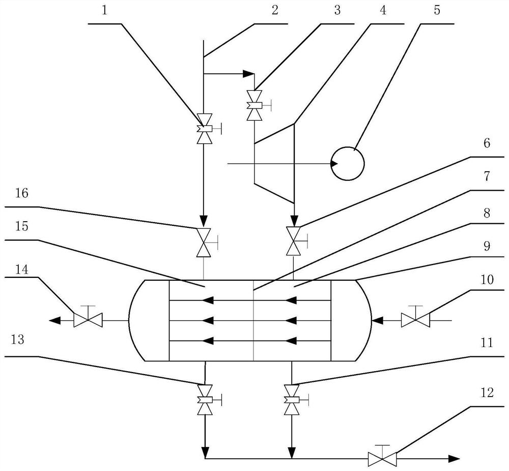
[0021] see figure 1 , the present invention includes a heating steam regulating valve 1, a heating steam pipeline 2, a small back pressure machine inlet steam regulating valve 3, a small back pressure machine 4, a driven device 5, a low pressure steam inlet valve 6, and a heater partition plate 7 , heater low-pressure stage 8, two-stage heating net...


PUM


Abstract

An energy gradient utilization system comprises a heat supply steam pipeline and a two-stage heat supply network heater. A heater partition plate used for dividing the two-stage heat supply network heater into a heater low-pressure stage and a heater high-pressure stage is arranged in the two-stage heat supply network heater, a heater water inlet pipeline connected with the heater low-pressure stage is arranged at one end of the two-stage heat supply network heater, and a heater water outlet pipeline connected with the heater high-pressure stage is arranged at the other end of the two-stage heat supply network heater. An outlet of the heat supply steam pipeline is divided into two paths, one path communicates with the heater high-pressure stage, the other path is connected with an inlet of a small back pressure machine, and an outlet of the small back pressure machine communicates with the heater low-pressure stage. By arranging the small back pressure machine and the two-stage heat supply network heater, heat supply steam and steam exhausted by the small back pressure machine are exhausted to the high-pressure stage and the low-pressure stage of the two-stage heat supply network heater correspondingly, two strands of steam with different pressure grades are exhausted to one heat supply network heater, gradient utilization of energy is achieved through the small back pressure machine, and meanwhile gradient heating of heat supply network water through the heater low-pressure stage and the heater high-pressure stage is achieved.

Description

technical field [0001] The invention belongs to the heat supply field of thermal power plants, and in particular relates to an energy cascade utilization system. Background technique [0002] In order to effectively utilize energy, rationally utilize high-quality steam, and realize cascaded utilization of energy, thermal power plants have carried out more heat supply transformations of small back pressure machines in recent years. comprehensive energy efficiency. At the same time, it also brings corresponding problems. Affected by many factors, the steam that works through the small back pressure machine is often not all the steam. Generally, part of the steam works through the small back pressure machine, and part of the steam continues to be directly discharged into the heating network heater. Since the pressure of the steam after the work done by the small back pressure machine is reduced, if it is discharged into the same heating network heater as the original steam, th...

Claims


Application Information

Patent Timeline
Patent Type & Authority Applications(China)
IPC IPC(8): F28D7/16F28B9/08F22D1/00F22B37/50
CPCF28D7/16F28B9/08F22D1/00F22B37/50
Inventor 程东涛仇磊居文平马汀山吕凯谢天余小兵王东晔
Owner XIAN THERMAL POWER RES INST CO LTD
Why Eureka
Try Eureka