
Positioning bracket for assembling and processing aircraft wings

A technology for assembly and processing of wings, applied in aircraft assembly and other directions, can solve the problems of reduced work efficiency, work quality, a lot of manpower, poor stability, etc., to save labor intensity, facilitate docking and installation, and improve stability.

Inactive Publication Date: 2021-08-06
芜湖中科飞机制造有限公司
View PDF0 Cites 6 Cited by
  • Summary
  • Abstract
  • Description
  • Claims
  • Application Information

AI Technical Summary

Problems solved by technology

[0004] When installing the wing, because the wing has the "three major characteristics" of large span, large volume, and heavy weight, how to ensure the correct wing installation angle and wing dihedral angle when installing the wing has become the The important technical indicators and efficiency indicators of installation, the existing wing installation method is mostly to move the bracket to the installation place manually by multiple operators to prevent the wing from colliding with the fuselage, and install the machine by crane lifting and manual calibration. Wing, this method makes it inconvenient for the operator to place the wing on the bracket, not only requires a lot of manpower, but also cannot accurately ensure the stability of the wing during installation, thus resulting in a decrease in work efficiency and work quality during installation
[0005] Therefore, there is a need for a positioning bracket based on aircraft wing assembly and processing to solve the problem of inconvenient placement of the wing and poor stability when docking the wing with the fuselage

Method used


Image

  • Positioning bracket for assembling and processing aircraft wings
  • Positioning bracket for assembling and processing aircraft wings
  • Positioning bracket for assembling and processing aircraft wings

Examples


Embodiment Construction

[0045] The present invention will be further described below in conjunction with the examples.

[0046] The following examples are used to illustrate the present invention, but cannot be used to limit the protection scope of the present invention. The conditions in the embodiment can be further adjusted according to the specific conditions, and the simple improvement of the method of the present invention under the premise of the concept of the present invention belongs to the protection scope of the present invention.

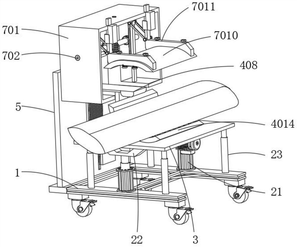
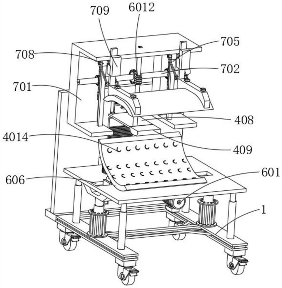
[0047] see Figure 1-9 , the present invention provides a positioning bracket based on the assembly and processing of aircraft wings, including a frame body 1, and the frame body 1 also includes a lifting mechanism 2, the lifting mechanism 2 is arranged on the top side wall of the frame body 1, and the lifting mechanism 2 is used for aligning the frame Adjust the height of body 1;

[0048] Further, the lifting mechanism 2 includes an oil cylinder 21, and the...


PUM


Abstract

The invention discloses a positioning bracket for assembling and processing based on aircraft wings and belongs to the technical field of aircraft wing mounting brackets. The positioning bracket comprises a frame body and a mounting plate a, wherein the frame body further comprises a lifting mechanism, the lifting mechanism is arranged on the side wall of a top end of the frame body, and the lifting mechanism is used for adjusting the height of the frame body; the mounting plate a is fixed to a side wall of one side of the frame body, a reset mechanism is arranged on the side wall of the side, adjacent to the frame body, of the mounting plate a, the reset mechanism is matched with the lifting mechanism to centralize the placed wing, and the pressing plate synchronously moves downwards so that the pressing plate clamps and limits a surface of the wing; through elasticity of a spring b, damage to the wing caused by clamping is reduced to a certain extent, abrasion caused in the clamping process is further avoided through the gasket, meanwhile, stability of the wing during wing installation and butt joint is further improved, and the situation caused by wing shaking is avoided.

Description

technical field [0001] The invention belongs to the technical field of mounting brackets for aircraft wings, and in particular relates to a positioning bracket for assembly and processing based on aircraft wings. Background technique [0002] The wing is one of the important parts of the aircraft and is installed on the fuselage. Its main function is to generate lift. At the same time, ammunition warehouses and fuel tanks can be arranged in the wings, and the landing gear can be stowed during flight. In addition, flaps for improving take-off and landing performance and used for aircraft The ailerons operated laterally, some are also equipped with slats and other lift-increasing devices on the leading edge of the wing; because the aircraft is flying in the air, it is very different from the general means of transportation and machinery. The various components of the aircraft are required to be as light as possible while satisfying the structural strength and rigidity, and th...

Claims


Application Information

Patent Timeline
Patent Type & Authority Applications(China)
IPC IPC(8): B64F5/10
CPCB64F5/10
Inventor 杨柳王超李传兵盛明虎周学松
Owner 芜湖中科飞机制造有限公司
Learn More