
An axis-shifting reversing dual-rotor aircraft

An aircraft and dual-rotor technology, applied in the field of aircraft, can solve the problems of increased aircraft height, complex control mechanism, and difficult maintenance, and achieve the effects of shortened rotor spacing, sensitive control, and reduced rotor diameter

Active Publication Date: 2022-08-09
四川迅联达智能科技有限公司
View PDF7 Cites 0 Cited by
  • Summary
  • Abstract
  • Description
  • Claims
  • Application Information

AI Technical Summary

Problems solved by technology

However, the control mechanism of the rotor part is too complicated, the maintenance is very difficult and the cost is high
When the cyclic pitch variable mechanism is used, the requirements for the structural strength of the rotor and the control mechanism are also very high. The horizontal hinges arranged in the rotor assembly of the cyclic pitch variable mechanism may interfere with each other when the state of the rotor changes. In order to prevent the occurrence of double propeller collision accidents The only way to improve safety is to increase the plane spacing of the two propellers, which increases the height of the aircraft and increases its volume. The development of the field; and the too long rotor shaft also affects the roll and pitch maneuverability of the aircraft

Method used


Image

  • An axis-shifting reversing dual-rotor aircraft
  • An axis-shifting reversing dual-rotor aircraft
  • An axis-shifting reversing dual-rotor aircraft

Examples


Embodiment 1

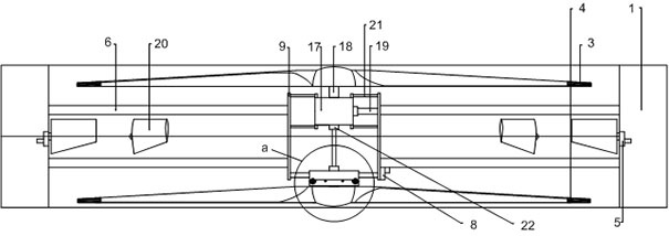
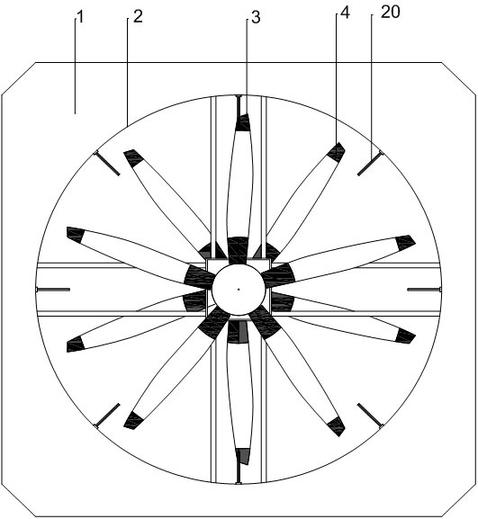
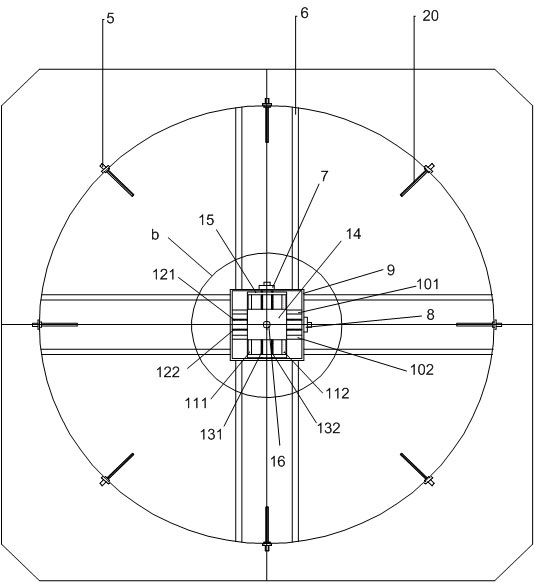
[0048] Example 1: as Figure 1 to Figure 11 As shown, an axis-shifting and reversing dual-rotor aircraft includes an aircraft power unit and a translation rotor assembly, and the translation rotor assembly includes a rotor, a universal joint transmission device and a translation device; the output end of the aircraft power device and The fixed point connection of the universal joint transmission device, the moving point of the universal joint transmission device is connected with the translation device, the translation device is connected with the rotor, and the moving point and translation device of the rotor and the universal joint transmission device can be along the Movement in the X-axis and / or Y-axis direction; the universal joint transmission device transmits the torsion force of the aircraft power device to the rotor, so as to drive the rotor to rotate.

[0049] In the prior art, the traditional cyclic pitch control system is used to increase the distance between the t...

Embodiment 2

[0059] Embodiment 2: This embodiment is further limited on the basis of Embodiment 1, such as Figure 12 to Figure 17 shown;

[0060] In this embodiment, it also includes an upper translation rotor assembly, a lower translation rotor assembly and a fixed rotor assembly. The fixed rotor assembly includes a rotor and a rotor drive shaft 18, and the output end of the aircraft power device is connected to the rotor through the rotor drive shaft 18. , used to control the rotor to rotate around itself; the upper output end of the aircraft power unit is used to connect the upper translation rotor assembly or the fixed rotor assembly, and the lower output end of the aircraft power unit is used to connect the lower translation rotor assembly or fixed rotor assembly , at least one upper translation rotor assembly or one lower translation rotor assembly is connected to the output end of the power device of the aircraft; in order to further improve its control accuracy, in this scheme, it...

Embodiment 3

[0061] Embodiment 3: This embodiment is further limited on the basis of Embodiment 1, such as Figure 18 to Figure 23 shown;

[0062] In the present embodiment, since the solution adopts fixed-pitch rotors and the rotational speed of the upper and lower rotors is the same, taking into account the needs of the aircraft heading control, it also includes a heading control wing 20 and a control wing servo 5, and the control wing servo 5 is provided in the overflow hole. 2. Outer side wall, the course control wing 20 is an airfoil with a biconvex symmetrical airfoil in section, the leading edge of the airfoil of the course control wing 20 faces the reverse direction of the rotor slip flow, and the airfoil of the course control wing 20 The direction of the trailing edge is the same as the direction of the rotor slipstream, the wing root of the heading control wing 20 is prefabricated with a rotating shaft that can change the angle of attack of the airfoil and fix the airfoil surface...


PUM


Abstract

The invention provides an axis-shifting and reversing dual-rotor aircraft, which includes an aircraft power device and a translation rotor assembly. The translation rotor assembly includes a rotor, a universal joint transmission device and a translation device; the output end of the aircraft power device and the universal joint The fixed-point connection of the transmission device, the connection between the moving point and the translation device of the universal joint transmission device, the connection between the translation device and the rotor, the moving point and the translation device of the rotor and the universal joint transmission device can all move along the X axis and / or the Y axis direction ; The universal joint transmission device transmits the torsion force of the aircraft power device to the rotor, which is used to drive the rotor to rotate. With this solution, fixed-pitch rotors are used to increase rotor speed, reduce rotor diameter, reduce aircraft volume, use fixed-pitch rotors to improve rigidity, and there is no cyclic pitch control system between rotors, the rotor spacing is greatly shortened, and the height is greatly reduced. The position of the tension line and the center of gravity is used to control the attitude of the aircraft with the lift-off pulling force, the control torque is large, and the aircraft is responsive.

Description

technical field [0001] The invention relates to the technical field of aircraft, in particular to an axis-shifting and reversing dual-rotor aircraft. Background technique [0002] The traditional coaxial twin-rotor aircraft is widely used for its advantages of high efficiency, good hovering stability, easy heading control and small size. However, the control mechanism of the rotor part is too complicated, maintenance is very difficult and the cost is high. When the cyclic pitch change mechanism is used, the requirements for the structural strength and control mechanism of the rotor are also very high. The horizontal hinges arranged in the rotor assembly of the cyclic pitch change mechanism may interfere with each other when the state of the rotor changes. It is only possible to increase the plane spacing of the two propellers to improve safety, which will increase the height of the aircraft and increase the volume. For example, the ship-borne Russian Ka series helicopters h...

Claims


Application Information

Patent Timeline
Patent Type & Authority Patents(China)
IPC IPC(8): B64C27/10B64C27/32B64D35/06
CPCB64C27/10B64C27/32B64D35/06Y02T50/40
Inventor 张弓
Owner 四川迅联达智能科技有限公司
Learn More