
Double-lead-screw-driven automatic turnover numerical control rotary table

A rotary table and automatic flip technology, applied in the direction of worktables, manufacturing tools, etc., can solve the problems that it is difficult to balance processing efficiency and precision at the same time, and cannot meet the needs of intelligent processing, so as to improve processing efficiency and processing accuracy, and stabilize the structure , good synchronization performance

Pending Publication Date: 2021-08-06
JIANGSU COLLEGE OF INFORMATION TECH
View PDF9 Cites 2 Cited by
  • Summary
  • Abstract
  • Description
  • Claims
  • Application Information

AI Technical Summary

Problems solved by technology

During processing, add tooling wedges on the horizontal worktable to raise the workpiece to a required angle relative to the table, or use a hydraulic cylinder to drive the table to turn over a certain angle, but these two methods are difficult to take into account the processing efficiency and accuracy at the same time. The current needs of intelligent processing

Method used


Image

  • Double-lead-screw-driven automatic turnover numerical control rotary table
  • Double-lead-screw-driven automatic turnover numerical control rotary table

Examples


Embodiment Construction

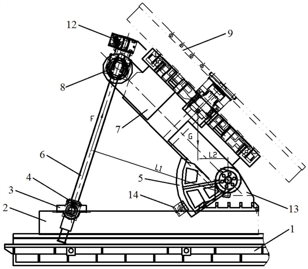
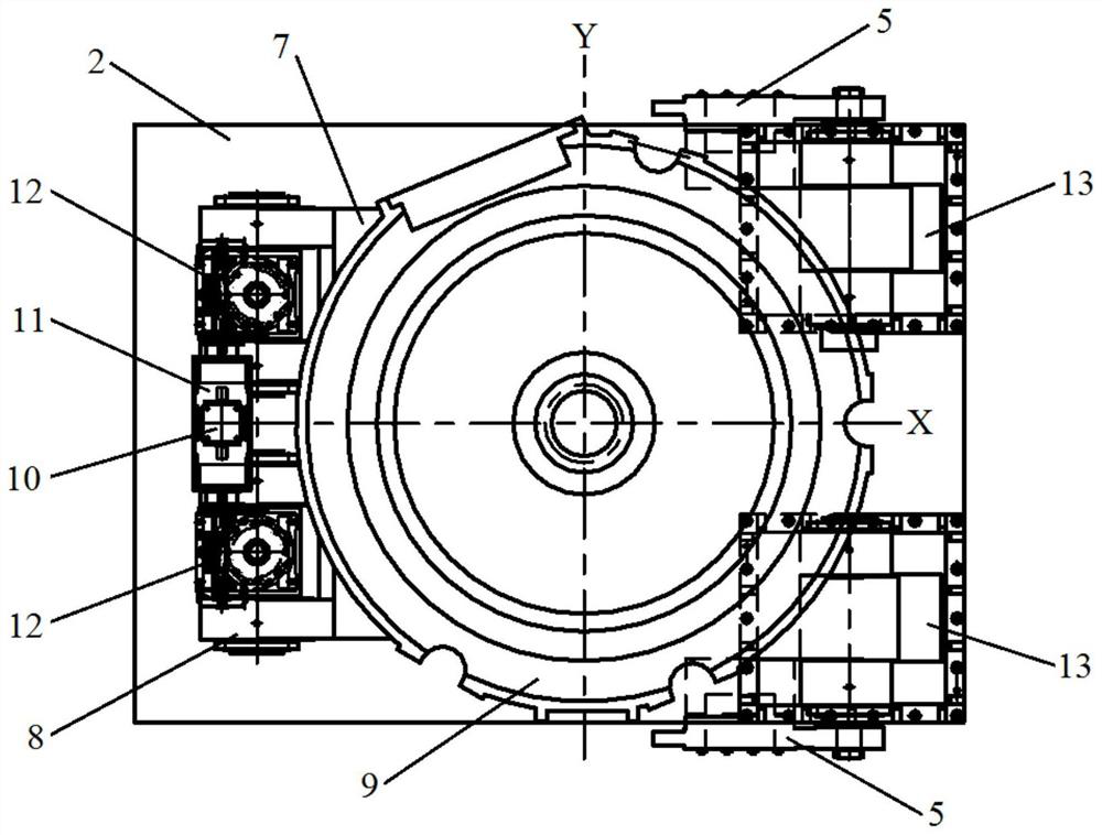
[0016] Regarding the aforementioned and other technical contents, features and effects of the present invention, refer to the appended figure 1 to attach figure 2 It will be apparent from the detailed description of the embodiments. The structural contents mentioned in the following embodiments are all based on the accompanying drawings of the description.

[0017] Exemplary embodiments of the present invention will be described below with reference to the accompanying drawings.

[0018] The dual-screw-driven automatic flip CNC rotary table provided by the present invention mainly solves the problem that the CNC rotary table top realizes automatic flip motion at any angle within the range of 0 to 45°, and can realize precise control of positioning accuracy and repeat positioning accuracy during the flipping process. . The solution is to adopt the servo motor-driven double-screw flip technology on the table of the rotary table, that is, to use a servo motor to connect the r...


PUM


Abstract

The invention discloses a double-lead-screw-driven automatic turnover numerical control rotary table. The double-lead-screw-driven automatic turnover numerical control rotary table comprises a lathe bed, a sliding base, a working table body, a supporting plate and lead screws, the sliding base is arranged on the lathe bed in a sliding mode, the supporting plate is connected to the working table body in a sliding mode, the working table body can rotate and slide on the supporting plate, the right end of the supporting plate is hinged to a support at the right end of the sliding base, and the left end of the sliding base drives the left end of the supporting plate to move around the arc of the support through the lead screws, so that the working table body is driven to automatically turn over. The double-lead-screw-driven automatic turnover numerical control rotary table has the advantages that a servo motor is adopted to be connected to a right-angle double-output-shaft speed reducer, then a second-stage right-angle speed reducer is driven to equally transmit power to the two lead screws, then the supporting plate is driven to drive a table board of the working table body to turn over and swing around the support, the structure is stable, the synchronism property is good, the problem of automatic turnover motion of the table board of the numerical control rotary table can be solved, accurate control over the positioning precision and the repeated positioning precision in the turnover process of the working table body can be realized, multi-procedure and multi-angle machining can be realized by installing and clamping a workpiece at a time, and the machining efficiency and the machining precision of the inclined surface and an inclined hole of the workpiece are improved.

Description

technical field [0001] The invention belongs to the field of processing equipment, in particular to a dual-screw-driven automatic flip numerical control rotary workbench. Background technique [0002] With the rapid development of my country's shipbuilding industry, the requirements for the machining accuracy and efficiency of the inclined plane and inclined hole of the workpiece are getting higher and higher. The traditional processing technology adopts the CNC rotary table combined with the CNC floor milling and boring machine for cutting and processing. The rotary table has two feed movements: the longitudinal movement of the slide seat and the rotation of the table. During processing, add tooling wedges on the horizontal worktable to raise the workpiece to a required angle relative to the table, or use a hydraulic cylinder to drive the table to turn over a certain angle, but these two methods are difficult to take into account the processing efficiency and accuracy at th...

Claims


Application Information

Patent Timeline
IPC IPC(8): B25H1/18
CPCB25H1/18
Inventor 崔凤有陈雪芳
Owner JIANGSU COLLEGE OF INFORMATION TECH
Learn More