A center hole punching device for milling end face of steering knuckle 45° inclined bed

A technology for punching center holes and steering knuckles

Active Publication Date: 2022-07-05
HUBEI TRI RING FORGING
View PDF4 Cites 0 Cited by
  • Summary
  • Abstract
  • Description
  • Claims
  • Application Information

AI Technical Summary

Problems solved by technology

[0003] Since the steering knuckle is a special-shaped part with a relatively complicated shape, it is difficult to clamp and position during processing. In the prior art, the center hole of the milling end face of the steering knuckle is to punch holes at both ends of the stem of the steering knuckle. This center hole is mainly used for the positioning of subsequent processing steps. The deviation of this center hole may easily lead to the deviation of subsequent processing steps. All subsequent processing steps need to be operated on the basis of the positioning of this center hole. , punching the center hole is a crucial section
When machining the center hole of the steering knuckle rod and the center hole of the disc, most of the existing technologies use machining centers and combined machine tools. Not only the equipment cost is relatively high, but also the machining accuracy is difficult to guarantee. A simple and efficient processing fixture that can guarantee product quality and production efficiency, so that it can be processed on a horizontal lathe, has become a problem that needs to be solved urgently

Method used


Image

  • A center hole punching device for milling end face of steering knuckle 45° inclined bed
  • A center hole punching device for milling end face of steering knuckle 45° inclined bed
  • A center hole punching device for milling end face of steering knuckle 45° inclined bed

Examples


Embodiment Construction

[0040] The technical solutions of the present invention will be clearly and completely described below with reference to specific embodiments. Obviously, the described embodiments are only some, but not all, embodiments of the present invention. Based on the embodiments of the present invention, all other embodiments obtained by persons of ordinary skill in the art without creative efforts shall fall within the protection scope of the present invention.

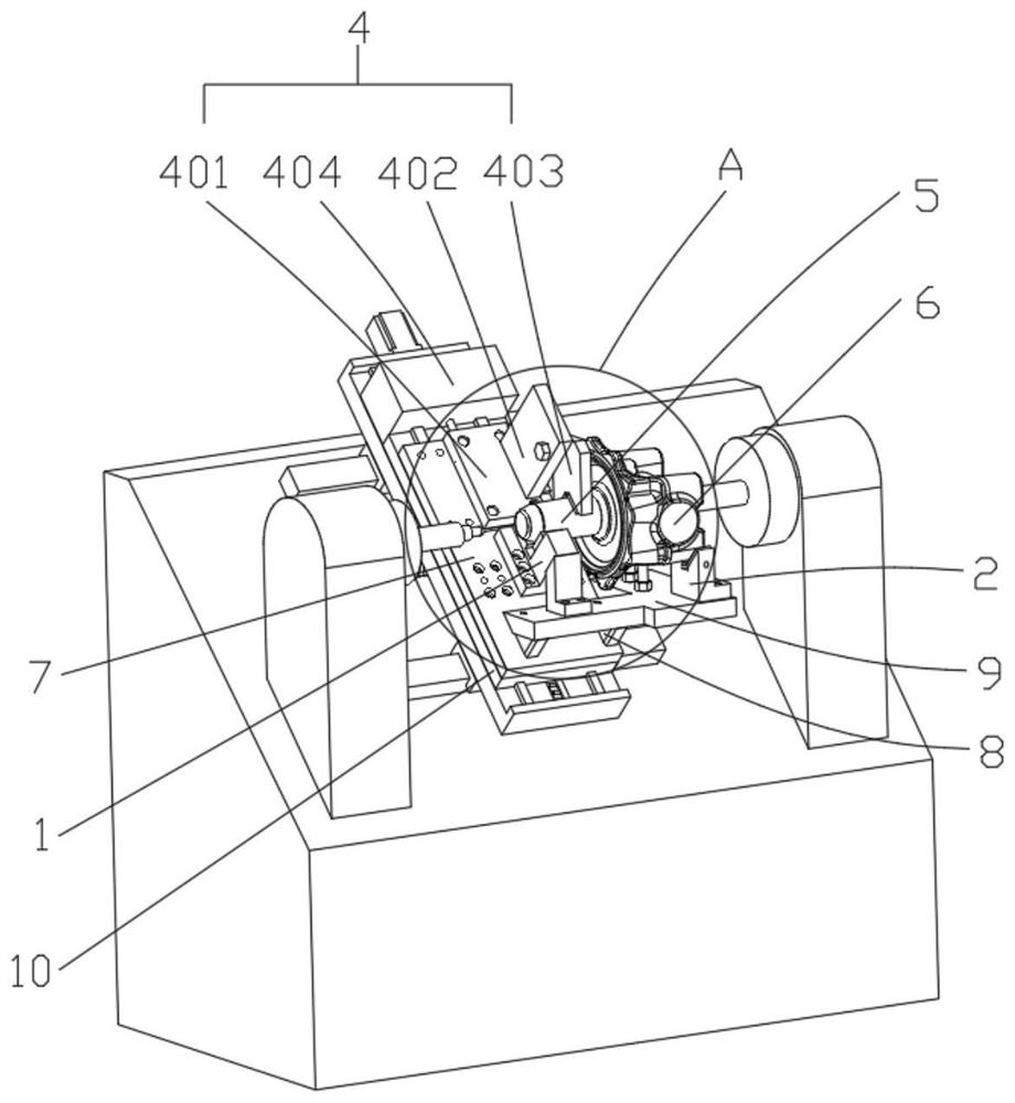
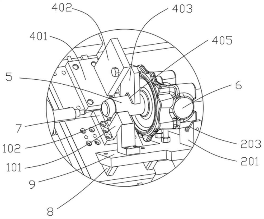
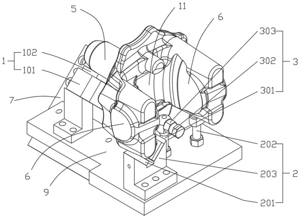
[0041] refer to figure 1 , a steering knuckle 45° inclined bed milling end face drilling center hole device, including a rod support part 1, an ear support part 2, a disk part positioning part 3 and a steering knuckle pressing part 4, the rod support part 1 Located below the steering knuckle rod 5, the ear support portion 2 is located below the steering knuckle ear 6, the disk positioning portion 3 is located on one side of the steering knuckle disk 11, the steering knuckle pressing portion 4 Located on one side of the stee...


PUM


Abstract

The invention relates to the field of steering knuckle processing devices, and discloses a steering knuckle 45° inclined bed milling end face drilling center hole device, which comprises a rod support part, an ear support part, a disk part positioning part and a steering knuckle pressing part. The rod support portion is located below the steering knuckle rod portion, the ear support portion is located below the steering knuckle ear portion, the disk portion positioning portion is located on one side of the steering knuckle disk portion, and the steering knuckle pressing portion is located in the steering knuckle. One side of the steering knuckle rod is supported from both ends of the steering knuckle through the rod supporting part and the ear supporting part. Using the fork structure of the steering knuckle, a triangular support is formed on the rod and ear of the steering knuckle, which has stable and stable , firm and not easy to shake, and then press the steering knuckle through the steering knuckle pressing part, so as to realize the positioning and clamping of the steering knuckle, and effectively ensure the uniqueness and stability of the position of the steering knuckle in the fixture after clamping. The clamping process is simple, the clamping effect and reliability are good, the precision is high, and the versatility is good.

Description

technical field [0001] The invention relates to the technical field of steering knuckle processing devices, in particular to a center hole drilling device for milling end faces of steering knuckles with a 45° inclined bed. Background technique [0002] The steering knuckle (claw) is one of the main parts on the steering axle of a car. Generally, the front axle of a truck is a steering axle. Its function is to bear the load of the front wheel of the car, support and drive the front wheel to rotate, etc. The steering knuckle is mainly composed of a steering knuckle rod. It is composed of parts such as the upper and lower ear parts, and the car braking system, steering system and suspension system are effectively connected through different parts, which play the dual tasks of steering and bearing, and transmit and bear the front load of the car. , supports and drives the front wheel to rotate around the kingpin to turn the car. [0003] Since the steering knuckle is a special-...

Claims


Application Information

Patent Timeline
Patent Type & Authority Patents(China)
IPC IPC(8): B23Q3/06
CPCB23Q3/06
Inventor 张运军童伟甘万兵王战兵张涛杜鑫艾然肖烈张从文张立宏黄朝
Owner HUBEI TRI RING FORGING
Why Eureka
Try Eureka