Brake pad automatic drilling drill bit positioning and installation mechanism and installation method thereof

A technology for positioning and installation, brake pads, applied in positioning devices, drilling/drilling equipment, boring/drilling and other directions, which can solve the problems of heavy labor, wear of card grooves, poor positioning and installation accuracy of drill bits, etc. , to achieve the effect of reducing labor and ensuring firm installation

Inactive Publication Date: 2021-08-06
湖北龙兴腾达汽车零部件有限公司
View PDF0 Cites 0 Cited by
  • Summary
  • Abstract
  • Description
  • Claims
  • Application Information

AI Technical Summary

Problems solved by technology

[0003] At present, most of the existing installation mechanisms require manual operation, which not only causes the installation of the drill bit to be not firm enough, but also causes a large amount of labor for the staff. At the same time, the existing installation mechanism does not have horizontal adjustment, resulting in the installation of the drill bit being unable to maintain a level. And then cause the drilling effect of the drill bit to be relatively poor, moreover the mode of the existing mounting mechanism mostly adopts the slot to temporarily fix the drill bit, which will easily cause the slot to wear after long-term use, and then cause the positioning and installation accuracy of the drill bit to be poor , so there is an urgent need for a new type of brake pad automatic drilling drill bit positioning and installation mechanism to solve these problems

Method used


Image

  • Brake pad automatic drilling drill bit positioning and installation mechanism and installation method thereof
  • Brake pad automatic drilling drill bit positioning and installation mechanism and installation method thereof
  • Brake pad automatic drilling drill bit positioning and installation mechanism and installation method thereof

Examples


Embodiment Construction

[0034] The present invention will be further described below in conjunction with accompanying drawing:

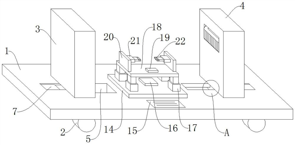
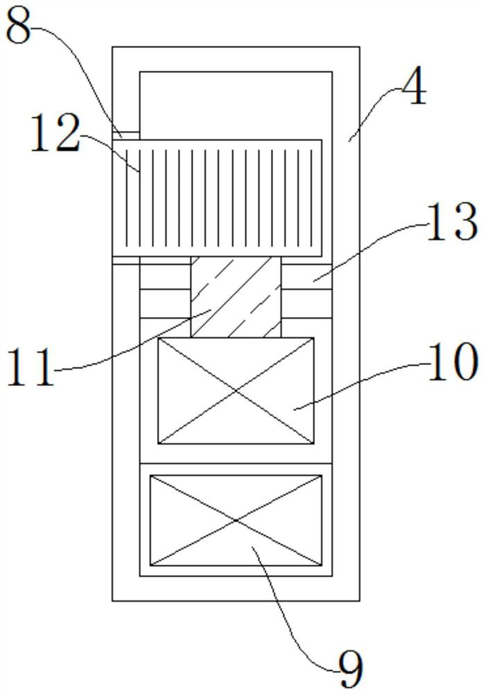
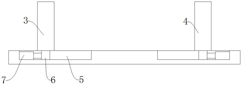
[0035] Such as Figure 1-Figure 4 As shown, a brake pad automatic drilling drill bit positioning and installation mechanism includes a base 1, a clamping column 3, a clamping column 2 4 and a level sensor 19, the four corners of the lower end of the base 1 are provided with rollers 2, and the base One side of the upper end of 1 is provided with the clamping column one 3, the other side of the upper end of the base 1 is provided with the clamping column two 4, the base 1 and the clamping column one 3 and the clamping column T-shaped chute 5 is respectively arranged at the junction of two 4, and T-shaped slide block 6 is all arranged at the junction of described clamping column one 3 and described clamping column two 4 and described T-shaped chute 5, and described T-shaped slide block 6 outsides are all provided with electric push rod one 7, are all provided with empty groov...


PUM


Abstract

The invention discloses a brake pad automatic drilling drill bit positioning and installation mechanism and an installation method thereof. The brake pad automatic drilling drill bit positioning and installation mechanism comprises a base, a first clamping column, a second clamping column and a horizontal sensor, and rolling wheels are arranged at the four corners of the lower end of the base. The brake pad automatic drilling drill bit positioning and installation mechanism and the installation method have the beneficial effects that through the design of the first clamping column, the second clamping column and a toothed belt, the installation mechanism can replace manual work, it can be ensured that a drill bit is firmly installed, and the labor amount of workers can be decreased. Through the design of a PLC, second electric push rods and the horizontal sensor, the installation mechanism can have a horizontal adjustment function, the drill bit can be horizontally installed, and therefore the drilling effect of the drill bit is ensured. Through the design of third electric push rods and rubber clamping blocks, the installation mechanism can be temporarily fixed in a clamping mode, the abrasion degree can be reduced, and replacement can be convenient and fast. Therefore, the positioning and installation precision of the drill bit can be ensured.

Description

technical field [0001] The invention relates to the technical field of drill positioning and installation, in particular to a brake pad automatic drilling drill positioning and installation mechanism and an installation method thereof. Background technique [0002] Drilling refers to leaving a cylindrical hole or hole on the target by means of rotary cutting or rotary extrusion with a tool that is harder and sharper than the target. It is often used in the drilling of brake pads Automatic drilling machine, and the automatic drilling machine needs to change the drill bit frequently in order to ensure the drilling effect and drilling efficiency. Therefore, most automatic drilling machines use self-tightening drill chucks to clamp the drill bit. In order to facilitate the drilling The replacement needs to use the drill positioning installation mechanism. [0003] At present, most of the existing installation mechanisms require manual operation, which not only causes the instal...

Claims


Application Information

Patent Timeline
Patent Type & Authority Applications(China)
IPC IPC(8): B23Q3/00B23B41/00B23Q17/22
CPCB23B41/00B23Q3/00B23Q17/2216
Inventor 马劲波陈小林彭广海彭广农
Owner 湖北龙兴腾达汽车零部件有限公司
Why Eureka
Try Eureka