
Bone injury adjuvant therapy device based on infrared therapy

A technology for adjuvant therapy and bone injury, applied in the field of infrared therapy, can solve the problems of eye discomfort, complicated operation, inability to automatically adjust the temperature of the infrared therapy device, etc., and achieve the effects of clear design ideas, convenient operation, and simple structure.

Active Publication Date: 2021-08-06
ZHENGZHOU UNIVERSITY OF LIGHT INDUSTRY
View PDF19 Cites 0 Cited by
  • Summary
  • Abstract
  • Description
  • Claims
  • Application Information

AI Technical Summary

Problems solved by technology

[0009] In view of the above situation, in order to overcome the defects of the prior art, the present invention provides a bone injury auxiliary treatment equipment based on infrared treatment, which effectively solves the problem of infrared treatment instrument irradiation When the patient has a wound, it is necessary to adjust the irradiation angle many times to prevent the patient's skin from being scalded during long-term local irradiation. Patients with problems that cause discomfort to their eyes

Method used


Image

  • Bone injury adjuvant therapy device based on infrared therapy
  • Bone injury adjuvant therapy device based on infrared therapy
  • Bone injury adjuvant therapy device based on infrared therapy

Examples


Embodiment 1

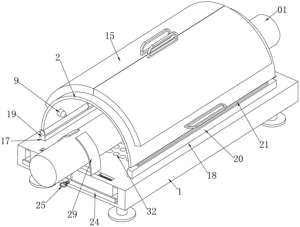
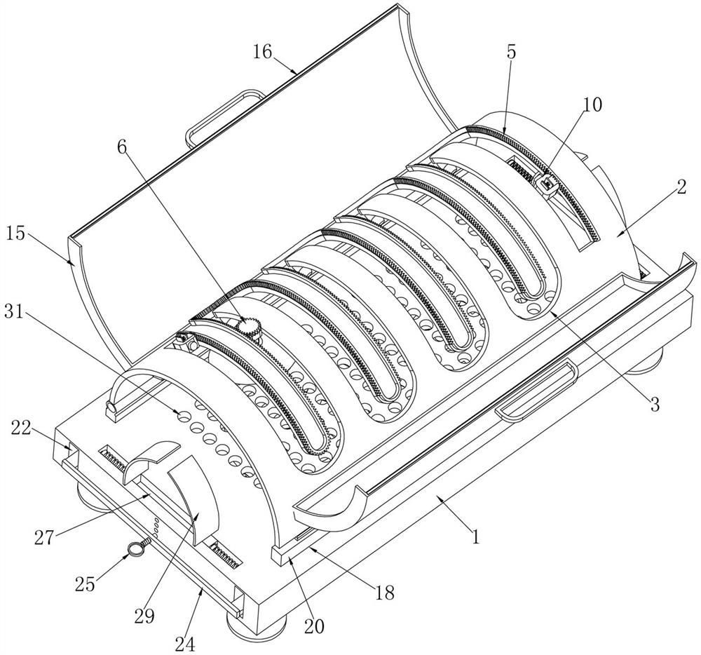
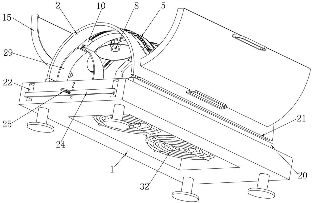
[0032] Embodiment 1. The present invention is an auxiliary bone injury treatment device based on infrared therapy. This device can be used for infrared auxiliary treatment on the limbs of patients, and includes a base 1 that can be placed on a bed or other carriers for use. Limbs 01 are placed on the base 1, and the patient's limbs (arms or legs) can be placed on the base 1 during use. It is characterized in that a semicircular plate 2 is hinged on the top of the base 1, and the semicircular plate The left side of 2 is hinged on the base 1, and its right side can be opened on the base 1. After opening, the patient's limbs can be placed on the base 1, and then the patient's limbs can be surrounded by closing the semicircular plate 2. The semicircular plate 2 There is a serpentine groove 3 running through the side wall, as attached Figure 5 As shown, the serpentine groove 3 is coiled on the semicircular plate 2 like a snake body, and a treatment slider 4 is slidably installed i...

Embodiment 2

[0034]Embodiment 2, on the basis of Embodiment 1, two switch sliders 10 located at the front and rear ends of the serpentine groove 3 are slidably installed in the serpentine groove 3, and the two switch sliders 10 can be placed in the serpentine groove 3. Sliding inside, the two switch sliders 10 are respectively fixed with travel switches 11, and the two travel switches 11 are respectively electrically connected to the controller. When the treatment slider 4 touches one of the travel switches 11, the controller will immediately The treatment motor 7 can be stopped and its reverse start can be controlled. At the same time, the positions of the two switch sliders 10 can be adjusted according to the length of the wound, so that the distance between the two switch sliders 10 in the serpentine groove 3 is changed, and the treatment slider 4 The stroke of sliding in the serpentine groove 3 is also changed, and the irradiation stroke of the infrared therapeutic device 8 is also chan...

Embodiment 3

[0035] Embodiment three, on the basis of embodiment two, the top of each of the switch sliders 10 is provided with a positioning chute 12, and each of the positioning chute 12 is slidably installed with a serpentine rack 5. Positioning racks 13, positioning springs 14 are installed between each positioning rack 13 and the corresponding positioning chute 12, and the positioning racks 13 can be connected to the serpentine rack 5 under the elastic force of the positioning springs 14. At this time, the switch slider 10 cannot move in the serpentine groove 3. When the positioning rack 13 is slid to disengage from the serpentine rack 5, the positioning spring 14 is compressed to store force. At this time, the switch slider 10 can Move and adjust its position in the serpentine groove 3.


PUM


Abstract

The invention provides a bone injury adjuvant therapy device based on infrared therapy. The problems that an infrared therapeutic apparatus needs to adjust the angle for multiple times to prevent the skin of a patient from being scalded, and operation is complex are solved. The bone injury adjuvant therapy device comprises a base, wherein a semicircular plate is hinged to the top of the base; a snakelike groove penetrates through the side wall of the semicircular plate; a therapy sliding block is installed in the snakelike groove in a sliding mode; a snakelike rack is fixedly installed on the outer side face of the semicircular plate along one side of the snakelike groove; a therapy gear meshed with the snakelike rack is rotationally installed at the top of the therapy sliding block; a therapy motor is fixedly installed at the bottom of the therapy sliding block; a rotating shaft of the therapy motor penetrates through the therapy sliding block to be fixedly connected with the therapy gear; an infrared therapeutic apparatus is fixedly installed at the bottom of the therapy motor; and multiple temperature sensors are fixedly installed on the inner side face of the semicircular plate. By means of the infrared therapeutic apparatus circularly moving in the snakelike groove, the irradiation position and angle of the skin of the patient can be automatically adjusted while infrared therapy is conducted on the skin of the patient, and the patient can be prevented from being scalded during long-time local irradiation.

Description

technical field [0001] The invention relates to the technical field of infrared therapy, in particular to an auxiliary bone injury treatment device based on infrared therapy. Background technique [0002] Infrared rays are the ray that can penetrate deep into the skin and subcutaneous tissue among all sunlight, and it has been scientifically proven that far-infrared rays are close to the vibration frequency of cell molecules in the human body. Far-infrared rays can penetrate into the human body and interact with atoms and The molecules resonate, and the friction between the molecules caused by the resonance generates heat, which promotes the rise of the subcutaneous temperature, expands the microvessels, accelerates blood circulation, helps to remove harmful substances in the blood vessels and the body, promotes the metabolism of the human body, and relieves body pain. In addition, the penetration of far-infrared rays on human skin is only 0.01 to 0.1 cm, so far-infrared ray...

Claims


Application Information

Patent Timeline
IPC IPC(8): A61N5/06
CPCA61N5/0613A61N2005/0642A61N2005/0659
Inventor 李端
Owner ZHENGZHOU UNIVERSITY OF LIGHT INDUSTRY
Learn More