


Quick Research
Generate reliable direction feasibility study reports for your R&D in just a few steps.

Technical Q&A
Discover and master advanced knowledge NOW. Basics, ideas, possibilities, all at once.

Find Solutions
As an expert in R&D theories, this can generate solutions to your technical problems instantly.

Evaluate Feasibility
Analyze your overall solution with one click, know your potential R&D risks in advance.

Monitor Landscape
Get weekly tech updates, stay abreast of the latest tech innovations and key insights.
Low-temperature blood vessel protection device
A technology for protecting devices and blood vessels, applied in the field of medical equipment, can solve the problems of inability to achieve the expected effect of surgery, inability to accurately evaluate the cooling effect of blood in the blood vessels, and poor cooling effect, so as to improve the expected effect, the cooling effect is good, and the convenience control effect
- Summary
- Abstract
- Description
- Claims
- Application Information
AI Technical Summary
Problems solved by technology
Method used
Image


Examples
Embodiment 1
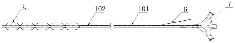
[0031] Such as Figure 1~6 As shown, the present invention provides a low-temperature blood vessel protection device, which includes a catheter 1 for intervening in blood vessels, and a fluid-filled channel 2 and a fluid-return channel 3 that are independent of each other and extend axially are arranged in the thick wall layer of the catheter 1 and a lateral channel 4; the outer wall of the head end of the catheter 1 is provided with a plurality of interconnected balloons 5, and the liquid filling channel 2 and the liquid return channel 3 are all communicated with the balloon 5; the lateral channel 4 is provided with a catheter for measuring 1. A temperature measuring sensor 6 for internal temperature. The temperature measuring sensor 6 is electrically connected to the external temperature display device. The number of balloons 5 is preferably but not limited to 4, and each balloon 5 is provided with a development mark. The developing marks can be detected by X-rays, so that ...
Embodiment 2
[0034] Such as Figure 1~6 As shown, this embodiment is further limited on the basis of Example 1. As a specific implementation of the liquid-filled channel 2 and the liquid-return channel 3 in the wall thickness layer of the catheter 1, the liquid-filled channel 2 and the adjacent The balloon 5 on the outer wall of the head end of the catheter 1 communicates, and the liquid return channel 3 communicates with the balloon 5 on the outer wall near the tail end of the catheter 1, so that the cooling liquid moves from the balloon 5 on the outer wall near the head end of the catheter 1 to the catheter 1 in turn. The balloon 5 on the outer wall of the tail end is reflowed to ensure that the cooling liquid first reaches the balloon 5 on the outer wall near the head end of the catheter 1; A specific embodiment, the liquid filling channel 2 communicates with the balloon 5 on the outer wall near the end of the catheter 1, and the liquid return channel 3 communicates with the balloon 5 o...
Embodiment 3
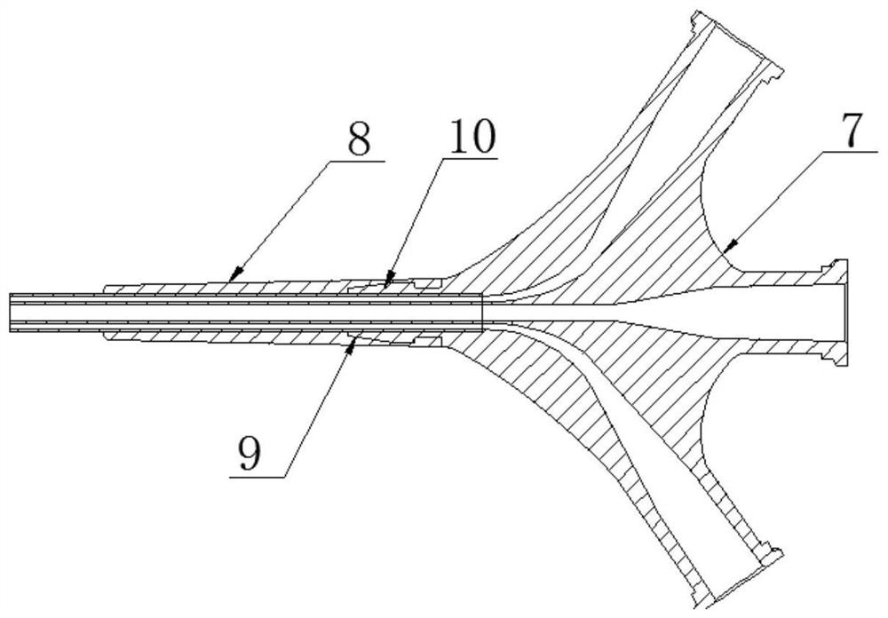
[0039] Such as Figure 1~6 As shown, this embodiment is further limited on the basis of implementation 2. The outer wall of the proximal tube body 101 is provided with a stress relief tube section 8, which is a hollow circular platform structure. The outer wall of the small diameter end of the stress release tube section 8 is The diameter is the same as the outer diameter of the distal tube body 102, and the inner wall of the large-diameter end of the stress release tube section 8 is provided with a card slot 9, and the catheter adapter 7 is provided with a buckle 10 that matches the card slot 9, and the large diameter of the stress release tube section 8 The diameter end is connected with the catheter base 7 through the engagement of the slot 9 and the buckle 10 . The stress relief pipe section 8 is used to transition the step on the catheter adapter 7, so that the connection between the catheter adapter 7 and the proximal tube body 101 is smoother, and when the protective de...
PUM
| Property | Measurement | Unit |
|---|---|---|
| Outer diameter | aaaaa | aaaaa |
| The inside diameter of | aaaaa | aaaaa |
Abstract
Description
Claims
Application Information
 - R&D Engineer
- R&D Manager
- IP Professional
- Industry Leading Data Capabilities
- Powerful AI technology
- Patent DNA Extraction
Browse by: Latest US Patents, China's latest patents, Technical Efficacy Thesaurus, Application Domain, Technology Topic, Popular Technical Reports.
© 2024 PatSnap. All rights reserved.Legal|Privacy policy|Modern Slavery Act Transparency Statement|Sitemap|About US| Contact US: help@patsnap.com