Axial-flow type check valve

A check valve, axial flow technology, used in valve details, control valves, valve devices, etc., can solve problems such as valve damage, reduced service life, large impact force on the sealing surface of the valve seat, and achieve reliable closing and sealing. The effect of improving the service life and reducing the impact

Inactive Publication Date: 2021-08-03
师海荣
View PDF4 Cites 0 Cited by
  • Summary
  • Abstract
  • Description
  • Claims
  • Application Information

AI Technical Summary

Problems solved by technology

The following problems often occur during the use of existing axial flow check valves: during the closing process of the valve clack, due to the fast closing speed, the impact force of the valve clack sealing surface on the sealing surface of the valve seat will be too large, which is easy to damage The sealing surface prevents the check valve from effectively shutting off and reduces the service life; at the same time, when the check valve disc is closed quickly, it is easy to generate water hammer, which leads to the occurrence of harmful situations such as damage to the valve.

Method used


Image

  • Axial-flow type check valve
  • Axial-flow type check valve
  • Axial-flow type check valve

Examples


Embodiment Construction

[0017] The present invention will be further described in detail below in conjunction with the accompanying drawings and embodiments.

[0018] Such as Figure 1-5 Shown is a preferred embodiment of the present invention.

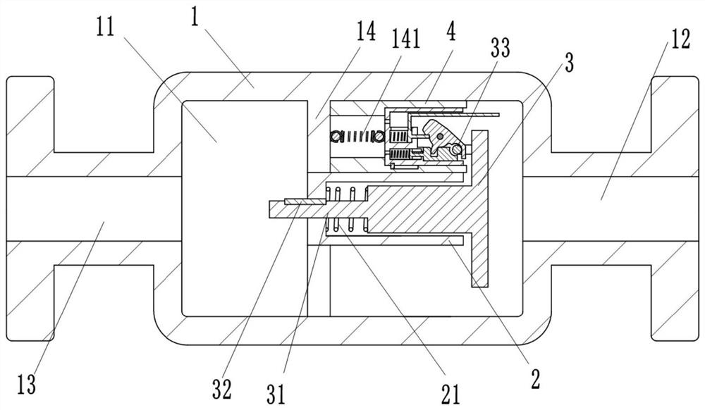
[0019] An axial flow check valve, including a valve body 1, a valve core barrel 2, a valve disc 3 and a buffer assembly 4; the valve body 1 is provided with a valve chamber 11, and the right side of the valve body 1 is provided with and The inlet pipe 12 communicating with the valve chamber 11, the left side of the valve body 1 is provided with the outlet pipe 13 communicating with the valve chamber 11; the middle part of the inner side wall of the valve chamber 11 is provided with a mounting plate 14; the lower end of the mounting plate 14 A spool cylinder 2 with an opening at the right end is horizontally provided; a first through hole is horizontally provided on the left end surface of the spool cylinder 2; a first keyway is provided in the first through...


PUM


Abstract

The invention relates to an axial-flow type check valve which comprises a valve body, a valve element barrel, a valve clack and a buffering assembly. A valve cavity is formed in the valve body, an inlet pipe communicating with the valve cavity is arranged on the right side of the valve body, and an outlet pipe communicating with the valve cavity is arranged on the left side of the valve body. A mounting plate is arranged in the middle of the inner side wall of the valve cavity. The valve element barrel with the right end being open is horizontally arranged at the lower end of the mounting plate. A first through hole is horizontally formed in the left side end face of the valve element barrel in a penetrating manner. A first key groove is formed in the first through hole. One end of the valve clack extends leftwards to be provided with a valve element rod connected with the first through hole in a sliding manner, and the valve element rod is arranged in the first through hole in a sliding fit manner through a first flat key. A first spring is arranged between the valve element barrel and the valve clack and used for forcing the valve clack to move rightwards to close the inlet pipe. The buffering assembly is horizontally arranged on the upper side of the valve element barrel and fixedly connected to the right end face of the mounting plate. A round rod is horizontally arranged on the right portion of the valve clack, and the axis of the round rod is perpendicular to the axis of the valve element rod. The buffering assembly is arranged in the valve, and therefore a water hammer can be avoided, impact can be reduced, and the service life of the valve clack can be prolonged; and when the valve clack is completely closed, the buffering assembly is separated from the valve clack, sealing of the valve clack cannot be affected, and the valve clack can be reliably closed and sealed.

Description

technical field [0001] The invention belongs to the field of pipeline valves, in particular to an axial flow check valve. Background technique [0002] The axial flow check valve is favored by engineering design because of its strong flow capacity, small flow resistance, no jamming in opening and closing, and reliable sealing. According to the classification of the valve core structure, the axial flow check valve can be divided into ring type and disc type. Working principle of axial flow check valve: The opening and closing of the disc is determined by the pressure difference between the inlet and outlet of the valve. When the pressure at the inlet port is greater than the sum of the pressure at the outlet port and the spring force, the disc opens. The following problems often occur during the use of existing axial flow check valves: during the closing process of the valve clack, due to the fast closing speed, the impact force of the valve clack sealing surface on the sea...

Claims


Application Information

Patent Timeline
Patent Type & Authority Applications(China)
IPC IPC(8): F16K15/06F16K47/00F16K47/02
CPCF16K15/063F16K47/00F16K47/023
Inventor 冯利敏张振国李长东
Owner 师海荣
Why Eureka
Try Eureka