
Centrifugal pump capable of conveniently adjusting direction of water outlet

A centrifugal pump and water outlet technology, which is applied to components, pumps, and pump components of a pumping device for elastic fluids, can solve the problems of reduced work efficiency, time-consuming and labor-intensive, low practicability, etc., and achieves improved work efficiency, Ease of installation and enhanced usability

Pending Publication Date: 2021-08-03
涂文奇
View PDF0 Cites 3 Cited by
  • Summary
  • Abstract
  • Description
  • Claims
  • Application Information

AI Technical Summary

Problems solved by technology

[0004] The purpose of the present invention is to solve the disadvantages in the prior art that it is cumbersome to change the direction of water flow or change the delivery location, time-consuming and labor-intensive, with a large workload, and it is impossible to deliver to multiple locations at the same time, reducing work efficiency and low practicability , and a centrifugal pump that is convenient to adjust the outlet direction is proposed

Method used


Image

  • Centrifugal pump capable of conveniently adjusting direction of water outlet
  • Centrifugal pump capable of conveniently adjusting direction of water outlet
  • Centrifugal pump capable of conveniently adjusting direction of water outlet

Examples


Embodiment 1

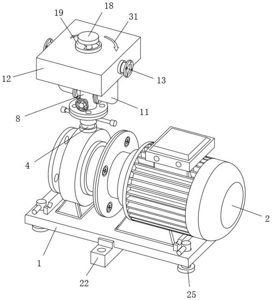
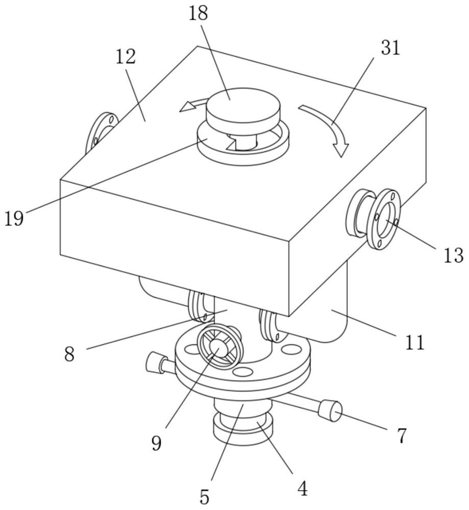
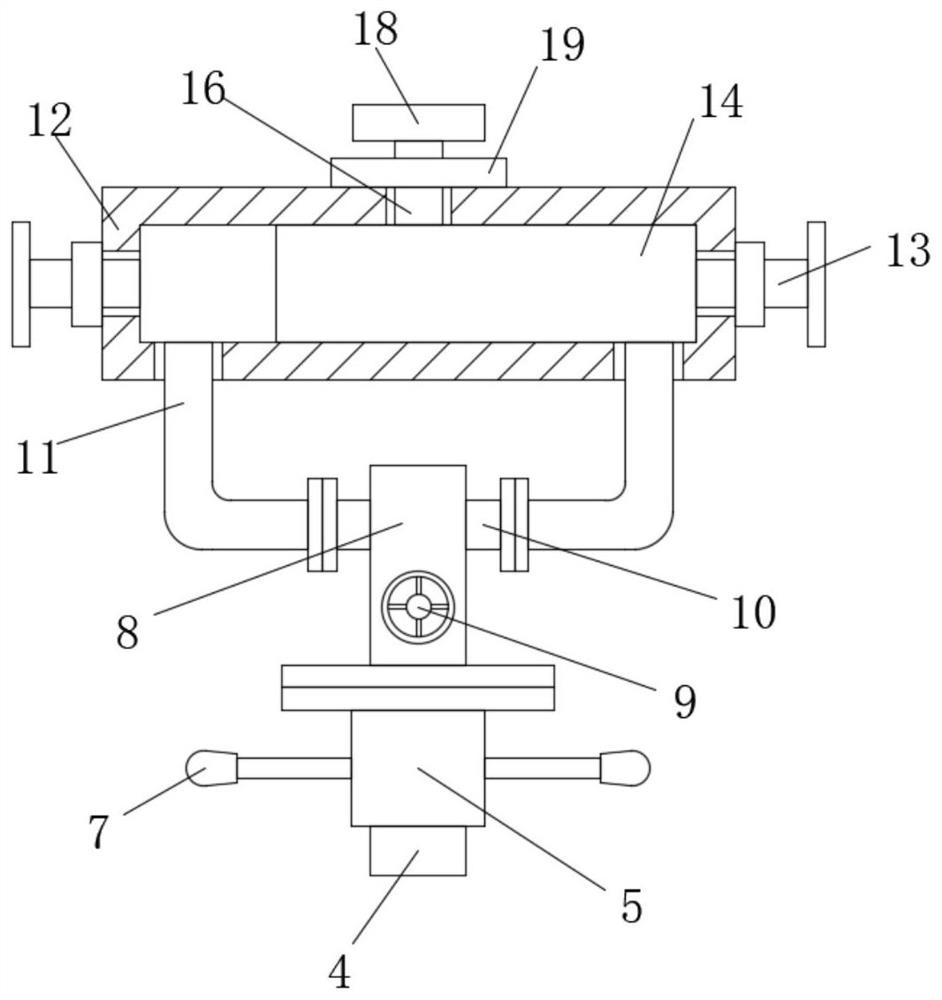
[0036] refer to Figure 1-10 , a centrifugal pump that is convenient to adjust the direction of the water outlet, including a bottom plate 1, the top of the bottom plate 1 is fixedly connected with a pump body 2, the pump body 2 is respectively provided with a water inlet 3 and a water outlet 4, and the water outlet 4 is sealed with a rotating sleeve A casing 5 is provided, the top of the casing 5 is flange-connected with a connecting pipe 8, and the top of the connecting pipe 8 is airtightly arranged, a valve 9 is provided on one side of the connecting pipe 8, and a valve 9 is arranged on one side of the connecting pipe 8 symmetrically. Two first connection ports 10, the ends of the two first connection ports 10 far away from each other are flange-connected with an L-shaped water delivery pipe 11, and the upward ends of the two L-shaped water delivery pipes 11 are fixedly connected with the same box body 12, the box Two second connection ports 13 are symmetrically arranged on...


PUM


Abstract

The invention belongs to the technical field of centrifugal pumps, and particularly relates to a centrifugal pump capable of conveniently adjusting the direction of a water outlet. For solving the problems that in the prior art, when the water flow direction is changed or a conveying place is replaced, the operation is troublesome, time and labor are wasted, the workload is large, conveying cannot be carried out at multiple places simultaneously, the working efficiency is reduced, and the practicability is low, the following scheme is proposed. The centrifugal pump comprises a bottom plate, a pump body is fixedly connected to the top of the bottom plate, the pump body is provided with a water inlet end and a water outlet end, the water outlet end is rotationally sleeved with a casing pipe in a sealed mode, and a connecting pipe is connected to the top end of the casing pipe through a flange. According to the centrifugal pump, the angle of a box body can be adjusted by rotating pusing rods, so that pipeline installation and traction are convenient; by rotating a rotary knob, not only can the one-way flowing direction of water flow be adjusted, but also the two-way conveying effect can be achieved, the working efficiency is improved, and practicability is high; and through sliding of an installing plate, installation is convenient , and overall movement and adjustment of the pump body can be facilitated.

Description

technical field [0001] The invention relates to the technical field of centrifugal pumps, in particular to a centrifugal pump which is convenient for adjusting the direction of a water outlet. Background technique [0002] Centrifugal pumps have various forms such as vertical, horizontal, single-stage, multi-stage, single-suction, double-suction, and self-priming. Centrifugal pumps work by rotating the impeller to cause the water to move centrifugally. Before starting the pump, the pump casing and the suction pipe must be filled with water, and then the motor is started to drive the impeller and the water to rotate at a high speed. The water undergoes centrifugal motion and is thrown to the outer edge of the impeller, and flows through the volute pump casing. The pressure water pipeline flowing into the water pump. [0003] Existing centrifugal pumps are usually only designed to discharge water from one water outlet. When it is necessary to change the direction of water fl...

Claims


Application Information

Patent Timeline
Patent Type & Authority Applications(China)
IPC IPC(8): F04D29/42F04D29/66F04D15/00F04D29/62F16M11/32F16M11/36F16F15/067
CPCF04D29/4293F04D29/669F04D15/0022F04D29/628F16M11/32F16M11/36F16F15/067
Inventor 涂文奇孙移晓
Owner 涂文奇
Learn More