Bulk cement storage and recovery silo

A technology for bulk cement and recycling cylinders, applied in packaging, loading/unloading, transportation and packaging, etc., can solve the problems of poor use effect, inability to achieve zero discharge and cement recycling, etc., achieve simple structure, eliminate air pollution, use handy effect

Active Publication Date: 2021-08-03
CHINA STATE CONSTR PORT ENG GRP
View PDF7 Cites 0 Cited by
  • Summary
  • Abstract
  • Description
  • Claims
  • Application Information

AI Technical Summary

Problems solved by technology

However, this method is only suitable for larger-scale silo matrix use, and is not suitable for fewer silos on the construction site, and there is not much room for sedimentation when the cement is added to the last few silos , can not achieve the effect of zero emission and cement recovery, the use effect is poor

Method used


Image

  • Bulk cement storage and recovery silo
  • Bulk cement storage and recovery silo
  • Bulk cement storage and recovery silo

Examples


Embodiment 1

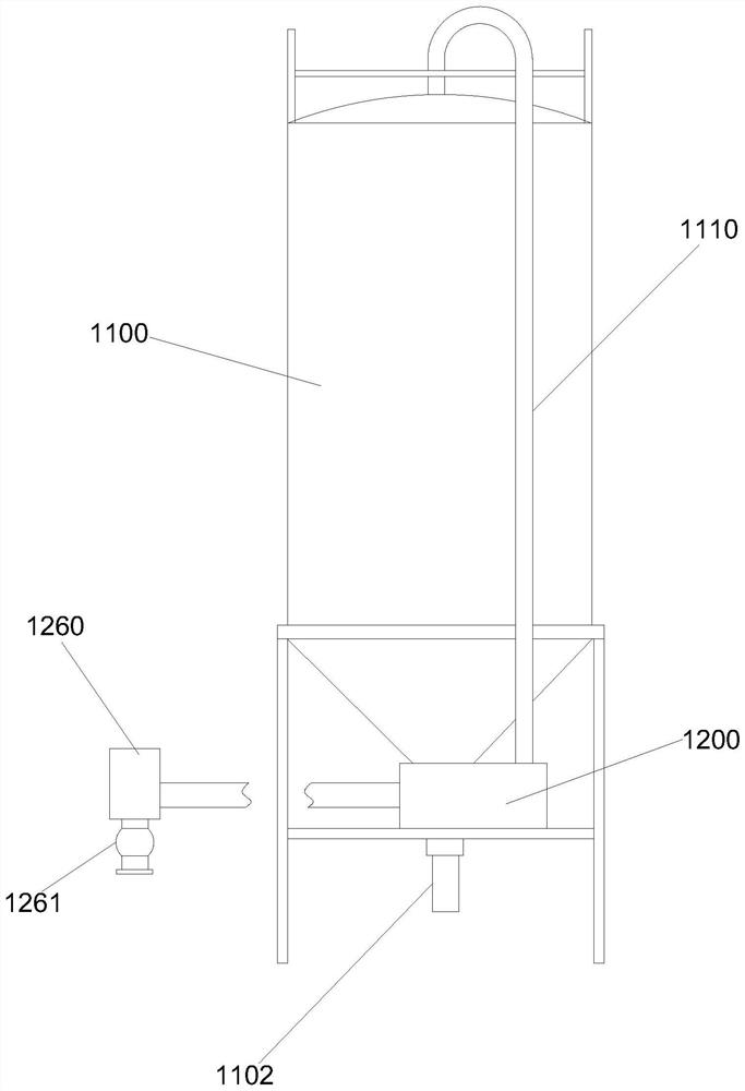
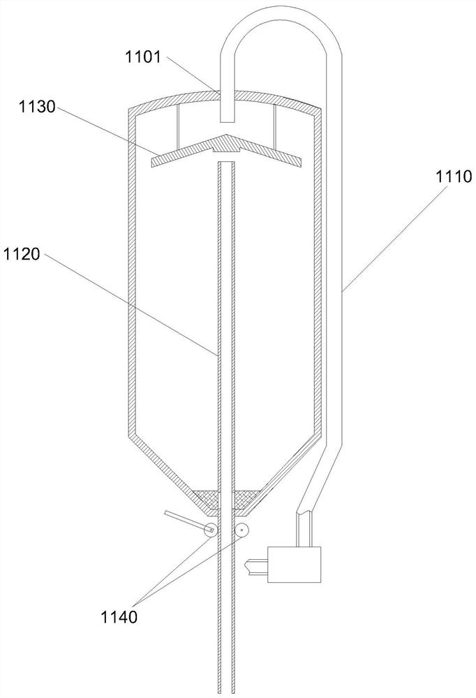
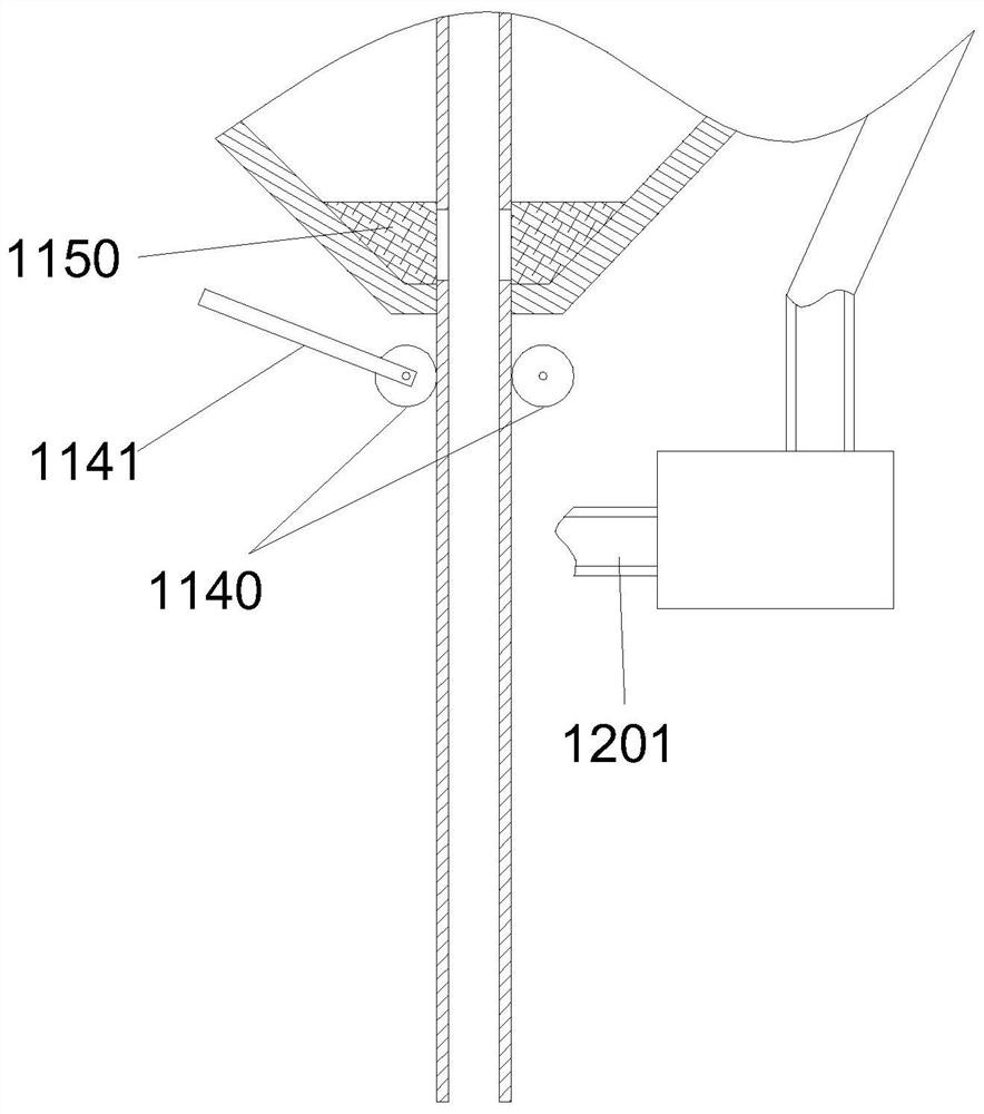
[0044] Such as Figure 1 to Figure 7 As shown, the bulk cement storage and recovery silo in this embodiment includes a cylinder body 1100, the top of the cylinder body 1100 is provided with a vent hole 1101, and the bottom of the cylinder body 1100 is provided with a discharge port 1102. The discharge port 1102 is connected to the transfer tank (not shown in the figure), and the exhaust hole 1101 is communicated with an exhaust supercharging mechanism 1200 through an exhaust pipeline 1110; the exhaust supercharging mechanism 1200 includes an exhaust pump 1210, Filter box 1220 and air compressor 1260, the air inlet of the exhaust pump 1210 is connected to the exhaust pipeline 1110, the outlet of the exhaust pump 1210 is connected to the filter box 1220, and the outlet of the filter box 1220 is connected to To the air compressor 1260 , the outlet of the air compressor 1260 is connected to the transfer tank through a one-way valve 1261 .

[0045]Through the scheme of this embodi...

Embodiment 2

[0066] Such as Figure 8 As shown, the bulk cement storage and recovery silo in this embodiment is based on the technical solutions in the above embodiments, and a transition box 1300 is fixed below the cylinder body 1100, and the bottom end of the discharge 1120 extends into the transition box In 1300, the discharge pipe 1120 is slidingly connected to the transition box 1300, and the transition box 1300 is connected to the transfer tank.

[0067] In the absence of the transition box 1300, the discharge pipe 1120 is directly connected to the transfer tank through a hose. In actual use, the efficiency of the hose will be reduced due to bending, and the left and right shaking of the hose will also be damaged due to friction. Therefore, after the transition box 1300 is adopted, the transfer tank and the transition box 1300 can be connected by hard pipes, and the cement is directly pumped into the transition box 1300, and then is pumped into the discharge pipe 1120 through the tra...


PUM


Abstract

The invention discloses a bulk cement storage and recovery silo. The silo comprises a silo body, an exhaust hole is formed in the top of the silo body, a discharging opening is formed in the bottom of the silo body, the discharging opening is connected into a transfer tank, the exhaust hole communicates with an exhaust pressurization mechanism through an exhaust pipeline, and an outlet of the exhaust pressurization mechanism extends into the transfer tank; the exhaust pressurizing mechanism comprises an exhaust pump and a filter box, an air inlet of the exhaust pump communicates with the exhaust pipeline, an outlet of the exhaust pump communicates with the filter box, and one end of the filter box communicates with the transfer tank. When filling is conducted on the silo body, air in the silo body is continuously extracted through the exhaust pressurizing mechanism and pressurized to be injected into the transfer tank, bulk cement in the transfer tank can enter the silo body from the discharging opening, dust generated in the silo body is mixed with the air and then enters the filter box through the exhaust pump to be filtered, and fine particles are discharged into the transfer tank again to be settled until the cement is completely injected into the silo.

Description

technical field [0001] The invention relates to the field of cement storage equipment, more specifically, to a storage and recovery silo for bulk cement. Background technique [0002] Bulk cement is usually stored in silos, and the powdered bulk cement is transported into the silo by high-pressure air in the transfer tank, and the air in the silo is discharged out of the silo through the vent hole at the top. However, since the discharged air is mixed with cement dust, dust removal treatment is required to avoid air pollution. [0003] The existing dust removal method is mainly to filter by setting a filter on the top of the silo. However, this method requires frequent maintenance, which increases the material cost and labor cost, and the dust removal effect is poor, and a large amount of fine dust will still be discharged into the air. , causing air pollution. [0004] With the call of the country for energy saving and emission reduction, there is also a more popular meth...

Claims


Application Information

Patent Timeline
IPC IPC(8): B65D88/54B65D88/08B65D90/00B65G69/18
CPCB65D88/08B65D88/548B65D90/00B65G69/182
Inventor 卞德晨刘其杰王晓华
Owner CHINA STATE CONSTR PORT ENG GRP
Why Eureka
Try Eureka