
Steel bar part welding and positioning device for building construction

A welding positioning and building construction technology, applied in the field of steel bar welding, can solve the problems of different diameter steel bars with different axes, low work efficiency, cold welding of steel bars, etc., to achieve the effects of different adjustment time, reduction of operation steps, and improvement of work efficiency

Active Publication Date: 2021-08-03
华新建工集团有限公司 +1
View PDF7 Cites 6 Cited by
  • Summary
  • Abstract
  • Description
  • Claims
  • Application Information

AI Technical Summary

Problems solved by technology

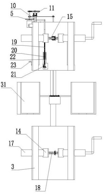
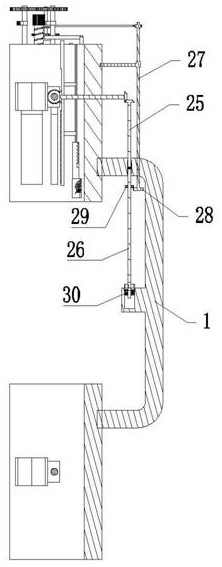
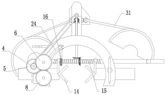
[0004] In order to solve the above-mentioned technical problems, the present invention provides a welding positioning device for steel bars used in building construction to solve the problem of low work efficiency caused by frequent disassembly of the device during the welding process of steel bars and the problem of misalignment after installation and clamping of steel bars with different diameters , In addition, it also solves the quality problems such as cold welding and false welding of steel bars after welding caused by different pressing timing and pressing distance when construction workers pressurize and upset

Method used


Image

  • Steel bar part welding and positioning device for building construction
  • Steel bar part welding and positioning device for building construction
  • Steel bar part welding and positioning device for building construction

Examples


Embodiment Construction

[0028] The following will clearly and completely describe the technical solutions in the embodiments of the present invention with reference to the accompanying drawings in the embodiments of the present invention. Obviously, the described embodiments are only some, not all, embodiments of the present invention. Based on the embodiments of the present invention, all other embodiments obtained by persons of ordinary skill in the art without making creative efforts belong to the protection scope of the present invention.

[0029] The following is attached Figure 1 to Figure 10 The specific implementation manner of the present invention will be described in further detail.

[0030]The welding and positioning device for steel bars for building construction includes a fixed rod 1 with a vertical axis. The upper end of the fixed rod 1 is connected with a first arc frame 2, and the lower end of the fixed rod 1 is connected with a The second arc frame 3, the first arc frame 2 is arc...


PUM


Abstract

The invention relates to a steel bar part welding and positioning device for building construction so as to solve the problems that in the welding process of steel bar electroslag pressure welding, a device is frequently disassembled, different-diameter steel bars are not coaxial after being installed and clamped, and the quality problem after steel bar welding is caused by operation of building workers during pressurizing and upsetting. The steel bar part welding and positioning device comprises a fixing rod with the axis vertically arranged, a first arc-shaped frame and a second arc-shaped frame are connected to the fixing rod, a first centering and clamping mechanism, a welding distance adjusting mechanism and a control system are arranged on the first arc-shaped frame, a second centering and clamping mechanism is arranged on the second arc-shaped frame, and a conductive agent box opening and closing mechanism is arranged on the fixing rod. By adjusting the welding distance adjusting mechanism, the problem that the welding distances of steel bars with different diameters are different is solved, a motor rotating speed switch is adjusted, the pressurizing and upsetting time of the steel bars with different diameters is adjusted, and in the pressurizing and upsetting process, the steel bar welding quality problem caused by the operation problem of workers is effectively avoided.

Description

technical field [0001] The invention relates to the field of steel bar welding, in particular to a welding positioning device for steel bar for building construction. Background technique [0002] In the welding of steel bars in the construction field, commonly used steel bar welding methods include flash butt welding, arc welding, electroslag pressure welding, resistance spot welding and steel bar pressure welding. Electroslag pressure welding is mostly used for vertical steel bars in cast-in-place reinforced concrete structural members. Take it long. The use method of prior art electroslag pressure welding: put a small piece of conductive agent (steel wire bead, electric welding rod, etc.) The arc is ignited and burned by the circuit. After the slag pool is formed, the steel bar is melted and the arc is stabilized for a certain period of time, while the power is turned off, the manual pressurization mechanism is used for pressurized upsetting to remove slag inclusions and...

Claims


Application Information

Patent Timeline
IPC IPC(8): B23K20/00B23K20/02B23K20/26B23K37/04B23K37/053
CPCB23K37/053B23K37/0443B23K20/002B23K20/02B23K20/26
Inventor 陈松李蓉包琳鲁晓建朱翔
Owner 华新建工集团有限公司
Learn More