Metal plate stamping device

A technology of sheet metal and stamping devices, applied in metal processing equipment, transportation and packaging, perforation tools, etc., can solve problems such as unfeasible solutions, and achieve the effect of avoiding high cost and low cost

Pending Publication Date: 2021-08-03
DONGFENG LIUZHOU MOTOR
View PDF15 Cites 0 Cited by
  • Summary
  • Abstract
  • Description
  • Claims
  • Application Information

AI Technical Summary

Problems solved by technology

[0004] The technical problem to be solved by the present invention is: it is not feasible to add punching parts with newly added holes on the existing mass production mold. The cost of mounting holes for parts is high and the cycle is long

Method used


Image

  • Metal plate stamping device
  • Metal plate stamping device
  • Metal plate stamping device

Examples


Embodiment Construction

[0034] The specific implementation manners of the present invention will be further described in detail below in conjunction with the accompanying drawings and embodiments. The following examples are used to illustrate the present invention, but are not intended to limit the scope of the present invention.

[0035] In describing the present invention, it should be understood that the terms "center", "longitudinal", "transverse", "upper", "lower", "front", "rear", "left", " The orientation or positional relationship indicated by "right", "vertical", "horizontal", "top", "bottom", "inner", "outer", etc. is based on the orientation or positional relationship shown in the drawings, and is only for the convenience of description The present invention and simplified description do not indicate or imply that the device or element referred to must have a specific orientation, be constructed and operate in a specific orientation, and thus should not be construed as limiting the present...


PUM


Abstract

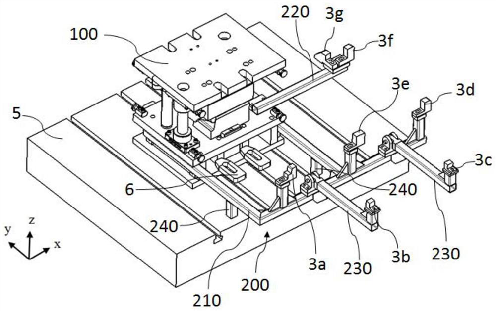
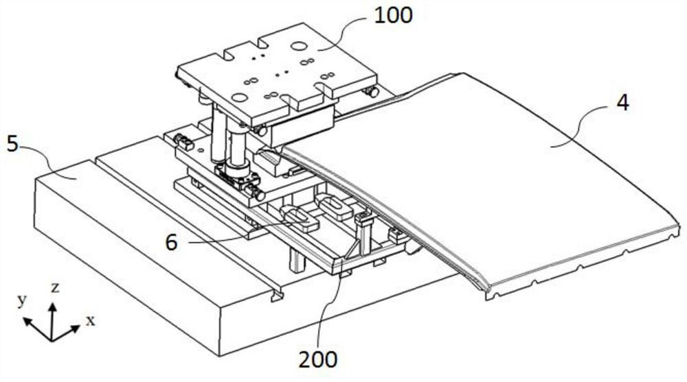
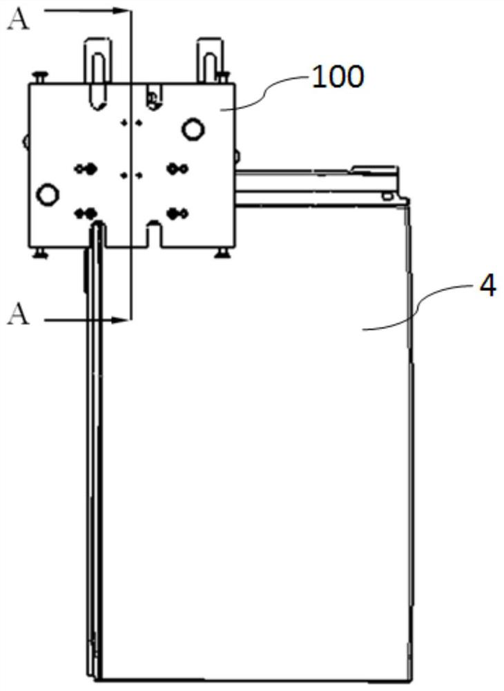
The invention relates to the technical field of automobile sheet metal part machining, and discloses a metal plate stamping device. The metal plate stamping device comprises a steel plate die, a bracket assembly and a supporting and positioning piece, wherein the steel plate die is used for blanking a metal plate; the bracket assembly extends from the steel plate die to the outside of the steel plate die; the supporting and positioning piece is adjustably connected to the bracket assembly and used for positioning and supporting the metal plate; and the bracket assembly and the supporting and positioning piece jointly act to position the metal plate to a station at which the steel plate die conducts blanking on the metal plate. According to the metal plate stamping device, the problem that the scheme that a punching part with a newly-added hole is additionally arranged on an existing mass production die is not feasible is solved, and the mode that a casting die with high manufacturing cost and long period is used is avoided.

Description

technical field [0001] The invention relates to the technical field of automobile sheet metal parts processing, in particular to a sheet metal stamping device. Background technique [0002] The optional accessories of some models require adding mounting holes on large and medium-sized sheet metal parts. Large and medium-sized sheet metal parts are usually processed in three steps, of which the first step is drawing forming, and the second step is edge trimming and punching , the third order is flanging and shaping. Combining the above-mentioned three-stage mold work content and mold structure analysis, it is difficult to realize the punching operation of adding holes by setting changes on the mold. Due to structural and space constraints, it is impossible to implement additional punching parts on existing mass-produced molds , so it is necessary to develop a new set of molds to implement the punching work of new holes in large and medium-sized sheet metal parts. [0003] H...

Claims


Application Information

Patent Timeline
Patent Type & Authority Applications(China)
IPC IPC(8): B21D28/34B21D28/26B21D28/04B21D28/14B21D37/04B21D53/88
CPCB21D28/34B21D28/26B21D28/04B21D28/14B21D37/04B21D53/88
Inventor 粟厚刚张瑞俊黄诚张锦宙符道光李厚洪陈彬彬展新
Owner DONGFENG LIUZHOU MOTOR
Why Eureka
Try Eureka