Clavicle middle section bone fracture plate

A technology of clavicle middle section and bone plate, which is applied in the field of medical devices, can solve problems such as difficult reduction and instability, and achieve the effects of facilitating fracture recovery, improving plasticity, and avoiding secondary fractures

Inactive Publication Date: 2021-08-03
SHANGHAI EAST HOSPITAL EAST HOSPITAL TONGJI UNIV SCHOOL OF MEDICINE
View PDF0 Cites 0 Cited by
  • Summary
  • Abstract
  • Description
  • Claims
  • Application Information

AI Technical Summary

Problems solved by technology

But generally fractures are shortened and displaced, and the surrounding ligaments, muscles, and tendons are stretched, which is very unstable and difficult to reset.

Method used


Image

  • Clavicle middle section bone fracture plate
  • Clavicle middle section bone fracture plate
  • Clavicle middle section bone fracture plate

Examples


Embodiment 1

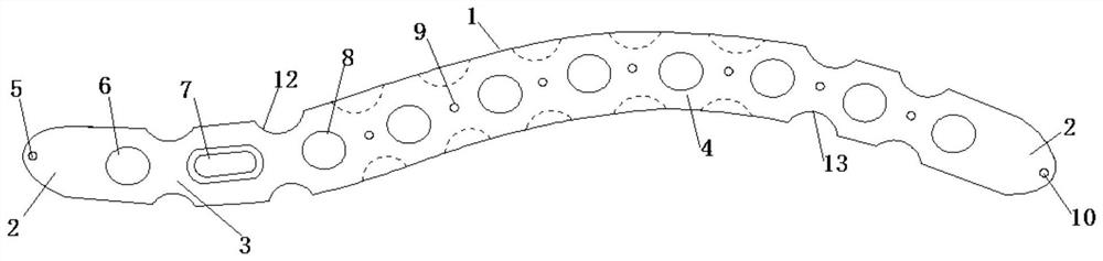
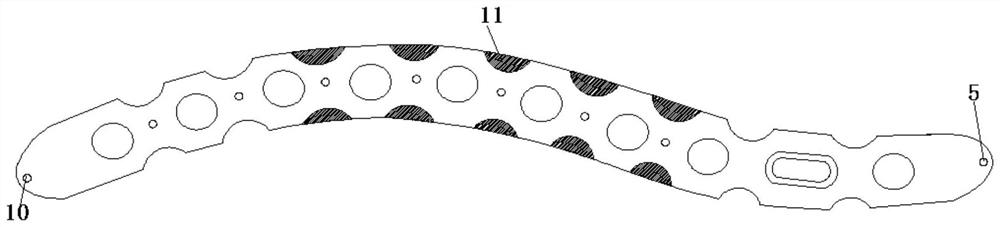
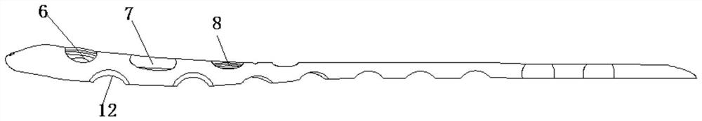
[0018] Such as Figure 1-Figure 3 A bone plate for the middle segment of the clavicle is shown, comprising a bone plate body 1, the two ends of the bone plate body 1 are shuttle-shaped structures 2, and the top end of the shuttle-shaped structure 2 is arc-shaped, so that the bone plate can be inserted and the operation is convenient. To reduce soft tissue irritation, the middle of the bone plate body 1 is an S-shaped structure, and the bone plate body 1 is divided into a segment proximal to the sternoclavicular joint 3 and a segment proximal to the acromioclavicular joint 4. The segment proximal to the sternoclavicular joint 3 is provided with near chest Kirschner wire hole 5, near chest locking hole 6 and sliding hole 7, and the near chest Kirschner wire hole 5 is located at the end of the proximal sternoclavicular joint section 3, and the near chest locking hole 6 is located at Between the proximal chest Kirschner hole 5 and the sliding hole 7, the proximal acromioclavicular...

Embodiment 2

[0020] Such as Figure 1-Figure 3 A bone plate for the middle segment of the clavicle is shown, comprising a bone plate body 1, the two ends of the bone plate body 1 are shuttle-shaped structures 2, and the top end of the shuttle-shaped structure 2 is arc-shaped, so that the bone plate can be inserted and the operation is convenient. The bone plate body 1 has a smooth curved surface structure to reduce friction with soft tissue and reduce postoperative discomfort. The middle of the bone plate body 1 is an S-shaped structure, and the bone plate body 1 1 is divided into a proximal sternoclavicular joint segment 3 and a proximal acromioclavicular joint segment 4. The proximal sternoclavicular joint segment 3 is provided with a proximal chest Kirschner wire hole 5, a proximal chest locking hole 6, and a sliding hole 7. The proximal chest The Kirschner wire hole 5 is located at the end of the proximal sternoclavicular joint segment 3, the proximal locking hole 6 is located between ...


PUM


Abstract

The invention discloses a clavicle middle section bone fracture plate which comprises a bone fracture plate body, the two ends of the bone fracture plate body are of fusiform structures, the top ends of the fusiform structures are in a circular arc shape, the middle of the bone fracture plate body is of an S-shaped structure, and the bone fracture plate body is divided into a proximal sternoclavicular joint section and a proximal acromioclavicular joint section. The proximal sternoclavicular joint section is provided with a proximal chest kirschner wire hole, a proximal chest locking hole and a sliding hole, the proximal chest kirschner wire hole is located at the end of the proximal sternoclavicular joint section, the proximal chest locking hole is located between the proximal chest kirschner wire hole and the sliding hole, the proximal acromioclavicular joint section is provided with a plurality of proximal shoulder locking holes, A proximal shoulderupper kirschner wire hole is formed between every two adjacent proximal shoulder locking holes, and a proximal shoulder lower kirschner wire hole is formed in the end of the proximal acromioclavicular joint section. The Kirschner wire holes are formed in the clavicle middle section bone fracture plate and can be used for temporary fixation, and the Kirschner wire holes in the two ends can be used for accurately positioning the bone fracture plate on the bone surface.

Description

technical field [0001] The invention relates to the technical field of medical devices, in particular to a mid-clavicle bone plate. Background technique [0002] The clavicle is S-shaped and rests between the manubrium and the acromion. It is the only bony skeleton connecting the lower and upper limbs to the torso. The clavicle is located under the skin and is superficial. It is prone to fracture when subjected to external force. The incidence rate accounts for 2.6% to 5% of all fractures in the whole body. Among them, the fracture of the middle part of the clavicle accounts for about 2 / 3 of the fractures of the entire clavicle, and most of them occur in children and young adults. Internal fixation is a method for the treatment of clavicle fractures. Among the internal fixation methods, the nail-plate system is one of the most commonly used internal fixation methods. The principle of internal fixation treatment is to make an incision at the broken end of the fracture, plac...

Claims


Application Information

Patent Timeline
IPC IPC(8): A61B17/80
CPCA61B17/8061A61B17/808
Inventor 刘立峰曹云飞方楠乔文泽李俊廷
Owner SHANGHAI EAST HOSPITAL EAST HOSPITAL TONGJI UNIV SCHOOL OF MEDICINE
Why Eureka
Try Eureka