Rotary device

A technology for rotating devices and housings, which is applied in the directions of transmission devices, electromechanical devices, transmission device parts, etc., and can solve the problems of warping, unstable gear tilting, abnormal noise of the housing, etc.

Pending Publication Date: 2021-07-30
MINEBEA CO LTD
View PDF1 Cites 0 Cited by
  • Summary
  • Abstract
  • Description
  • Claims
  • Application Information

AI Technical Summary

Problems solved by technology

[0004] However, in the rotary device disclosed in Patent Document 1, warpage due to shrinkage may occur when the first casing and the second casing are molded.
When at least one of the first case and the second case constituting the case is warped, the positions of the gears held by the case and the inclination of the gears are unstable, and when the motor rotates, the case vibrates to cause a difference. loud worry

Method used


Image

  • Rotary device
  • Rotary device
  • Rotary device

Examples


Embodiment Construction

[0033] Hereinafter, modes for implementing the present invention (hereinafter referred to as "embodiments") will be described in detail with reference to the drawings. In addition, in the whole description of embodiment, the same code|symbol is attached|subjected to the same component.

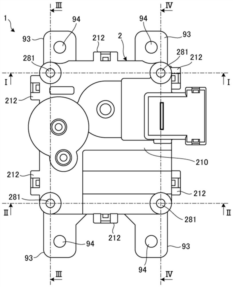
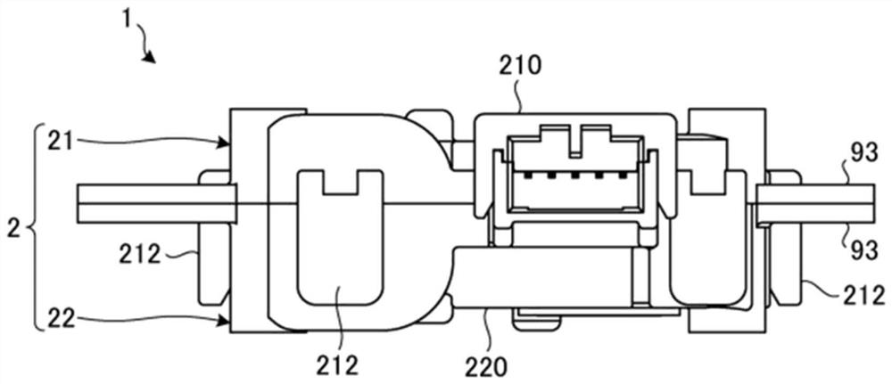
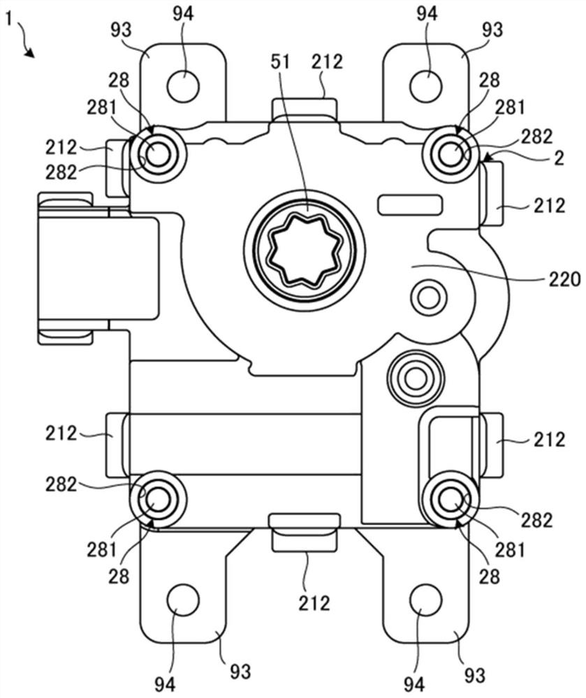
[0034] figure 1 is a plan view of the rotating device of the embodiment, figure 2 is a side view of the rotating device of the embodiment, image 3 It is a bottom view of the rotation device of embodiment. Figure 4A It is a perspective view with the first housing removed from the rotating device of the embodiment, Figure 4B It is the plan view which removed the 1st housing from the rotating device of embodiment. Figure 4C Yes Figure 4B A cross-sectional view of the V-V line, Figure 4D It is a perspective view of the second case of the rotation device of the embodiment. in addition, Figure 5 It is a perspective view of the first case of the rotation device of the embodiment.

[...


PUM


Abstract

The invention relates to a rotary device. The rotary device (1) according to an embodiment of the present invention is provided with: a casing (2) including a first case (21) and a second case (22) opposed to each other; a motor (3) housed in the casing (2); and a gear (5) that transmits the rotation of the motor (3) to the outside and that is housed in the casing (2). A tubular protrusion part (28) having a first through-hole (281) is formed in the first case (21), and a second through-hole (282) into which the protrusion part (28) is fitted is provided in the second case (22).

Description

technical field [0001] The present invention relates to rotating devices. Background technique [0002] Conventionally, there is known a rotating device (motor actuator) in which a motor and a gear set that transmits the rotation of the rotating shaft of the motor are accommodated in a housing composed of opposing first housings and second housings (refer to Patent No. Literature 1). Usually, the first case and the second case are molded with resin. [0003] Patent Document 1: Japanese Patent Laid-Open No. 2013-5512 [0004] However, in the rotary device disclosed in Patent Document 1, warpage due to shrinkage may occur when the first housing and the second housing are molded. When at least one of the first case and the second case constituting the case is warped, the positions of the gears held by the case and the inclination of the gears are unstable, and when the motor rotates, the case vibrates to cause a difference. Loud worry. Contents of the invention [0005] ...

Claims


Application Information

Patent Timeline
IPC IPC(8): H02K5/24H02K7/116F16H57/028
CPCH02K5/24F16H57/028F16H2057/02034F16H2057/0325F16H57/039F16H57/031F16H2057/02082H02K7/1166H02K5/225H02K2205/03H02K7/081F16H1/16H02K7/116
Inventor 平林晃一郎
Owner MINEBEA CO LTD
Why Eureka
Try Eureka