Air-cooled fuel cell power system of fixed-wing unmanned aerial vehicle

A power system and fuel cell technology, applied in the direction of fuel cells, fuel cell additives, fuel cell heat exchange, etc., can solve the problems of poor heat dissipation of the stack and low efficiency of the power system, and achieve improved power generation efficiency and unmanned aerial vehicles Endurance, eliminate energy consumption, and ensure the effect of heat dissipation requirements

Active Publication Date: 2021-07-30
UNIV OF ELECTRONIC SCI & TECH OF CHINA
View PDF14 Cites 1 Cited by
  • Summary
  • Abstract
  • Description
  • Claims
  • Application Information

AI Technical Summary

Problems solved by technology

[0006] Aiming at the problems of poor stack heat dissipation and low power system efficiency in the above-mentioned prior art, the present invention proposes an air-cooled fuel cell power system for a fixed-wing unmanned aerial vehicle, based on a new type of air-cooled fuel cell stack, using The controllable heat dissipation method combining the active cooling of the fan and the passive cooling of the air convection improves the power generation efficiency of the fuel cell system and the endurance of the drone

Method used


Image

  • Air-cooled fuel cell power system of fixed-wing unmanned aerial vehicle
  • Air-cooled fuel cell power system of fixed-wing unmanned aerial vehicle
  • Air-cooled fuel cell power system of fixed-wing unmanned aerial vehicle

Examples


Embodiment 1

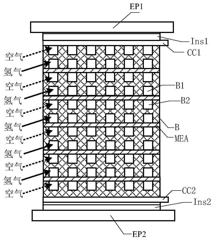
[0099] This embodiment provides an air-cooled fuel cell stack, such as figure 1 As shown, it includes anode end plate EP1, anode insulation plate Ins1, anode current collector CC1, multi-layer stacked bipolar plate B and membrane electrode MEA, cathode current collector CC2, cathode insulation plate Ins2 and cathode terminal Board EP2;

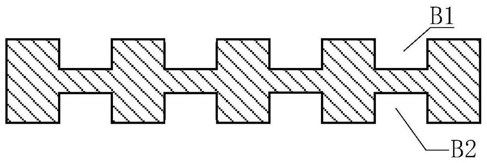
[0100] The processing material of the bipolar plate B can be a graphite plate, a composite plate or a metal plate, and the cross-sectional structure is as follows figure 2 As shown, the upper surface of the bipolar plate B is an anode, and a hydrogen flow channel B1 is provided for the fuel hydrogen flow reaction; the lower surface is a cathode, and an air flow channel B2 is provided for air circulation, in which the air is simultaneously used as an oxidant and a cooling medium ;

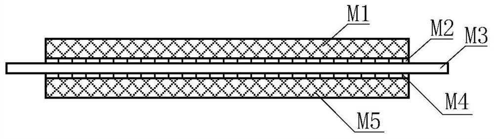
[0101] The membrane electrode MEA is the place where the electrochemical reaction occurs, and the cross-sectional structure is as follows image 3 As shown, the...


PUM


Abstract

The invention provides an air-cooled fuel cell stack. An air flow channel of the air-cooled fuel cell stack is a parallel wave-shaped flow channel. The invention further provides a fixed-wing unmanned aerial vehicle air-cooled fuel cell power system based on the parallel wave-shaped flow channel. The system comprises an air-cooled electric pile front flow guide module, a flow guide air inlet window, an air-cooled electric pile rear flow guide module, a flow guide air outlet window and a cooling fan; in order to control the reaction temperature of the galvanic pile to be within an ideal temperature interval, when the unmanned aerial vehicle is started or flies at a low speed, the cooling fan is started, and external air is sucked into the galvanic pile; during medium-speed flight, the cooling fan is closed, relative air flow formed during flight flows into a stack cathode air flow channel, stack outlet air flow is formed after reaction, and the cooling fan rotates passively; during high-speed flight, the cooling fan is closed, and the air inlet amount of relative air flow flowing into the electric pile is controlled by adjusting the opening size of the flow guide air inlet window. Fan active heat dissipation and air convection passive heat dissipation are combined, and the power generation efficiency and the cruising ability of the unmanned aerial vehicle are improved.

Description

technical field [0001] The invention belongs to the field of fuel cells, and in particular relates to an air-cooled fuel cell power system for a fixed-wing unmanned aerial vehicle. Background technique [0002] A fuel cell is an environmentally friendly, high-efficiency, long-life power generation device. Taking the proton exchange membrane fuel cell (PEMFC) as an example, the fuel gas enters from the anode side, the hydrogen atoms lose electrons at the anode and become protons, the protons pass through the proton exchange membrane to reach the cathode, and the electrons also reach the cathode through the external circuit, the cathode at the cathode Protons, electrons and oxygen combine to form water. The fuel cell converts chemical energy into electrical energy in a non-combustion manner, and its direct power generation efficiency can be as high as 45% because it is not limited by the Carnot cycle. With the battery stack as the core power generation device, the fuel cell ...

Claims


Application Information

Patent Timeline
IPC IPC(8): H01M8/0263H01M8/0267H01M8/04014H01M8/2457B60L50/64B60L58/33B64D27/24
CPCH01M8/0263H01M8/0267H01M8/04014H01M8/2457B64D27/24B60L50/64B60L58/33B60L2200/10B64U50/19Y02T10/70Y02T90/40Y02E60/50
Inventor 殷聪汤浩王仁康高艳李凯
Owner UNIV OF ELECTRONIC SCI & TECH OF CHINA
Why Eureka
Try Eureka