
Novel underneath type hydraulic machine

A hydraulic press, a new type of technology, applied in the field of hydraulic presses, can solve the problems of inconvenient assembly of the lifting height, shortening of the active power cylinder, etc.

Active Publication Date: 2021-07-30
河南泰田重工机械制造有限公司
View PDF3 Cites 0 Cited by
  • Summary
  • Abstract
  • Description
  • Claims
  • Application Information

AI Technical Summary

Problems solved by technology

[0003] In order to solve the above-mentioned problems, the object of the present invention is to propose a new type of hydraulic machine with a bottom, the power system and the hydraulic oil circuit system are arranged at the bottom of the hydraulic machine, and the power oil cylinders required for lifting are all fixed at the bottom of the hydraulic machine, which effectively solves the problem of the hydraulic machine. Inconvenient assembly due to the need for a large assembly lifting height during assembly. At the same time, the joint lifting structure of the movable upper beam and the movable middle beam is adopted, which shortens the formation of the main power cylinder, so that it can be compared with the traditional hydraulic machine under the same power condition. Can meet greater pressure output, optimize the use of power

Method used


Image

  • Novel underneath type hydraulic machine
  • Novel underneath type hydraulic machine
  • Novel underneath type hydraulic machine

Examples


Embodiment Construction

[0051] The content, characteristics and principles of the present invention will be further described below in conjunction with the accompanying drawings. The following descriptions are only examples, not limitations of the present invention.

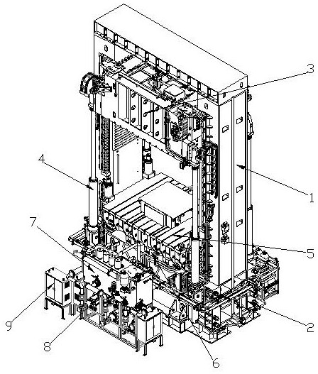
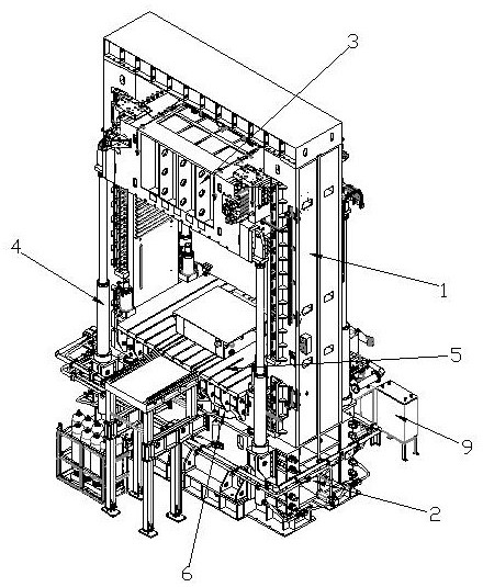
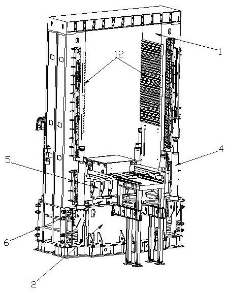
[0052] As shown in the figure, the present invention is a new type of undermounted hydraulic machine, which includes a column frame 1, a lower beam frame 2 arranged at the bottom of the column frame 1, and a movable upper beam 3 arranged on the column frame 1;

[0053] The four end corners of the lower beam frame 2 corresponding to the movable upper beam 3 are respectively vertically fixed with lifting cylinders 4 for pushing the movable upper beam 3 up and down, and the bottom end angles of the movable upper beam 3 are respectively connected to the corresponding The lifting cylinder 4 is connected;

[0054] The corners of the bottom of the movable upper beam 3 are respectively provided with support seats for assembling and connecting w...


PUM


Abstract

A novel underneath type hydraulic machine comprises a stand column frame, a lower beam frame and a movable upper beam. Lifting oil cylinders used for pushing the movable upper beam to ascend and descend are vertically and fixedly arranged at the positions, corresponding to the four end corners of the movable upper beam, of the lower beam frame correspondingly. The end corners of the bottom of the movable upper beam are connected with the corresponding lifting oil cylinders correspondingly. A movable middle beam is arranged on the stand column frame and located on the upper side of the lower beam frame, and a plurality of main power oil cylinders used for pushing the movable middle beam to ascend and descend are evenly and perpendicularly arranged at the position, located at the bottom of the movable middle beam, in the lower beam frame. An oil tank, a hydraulic pump station and a master control cabinet for controlling and driving the hydraulic machine to operate are arranged on one side of the lower beam frame. A holding mechanism used for fixing the lifting position of the movable upper beam and a guide mechanism used for guiding lifting of the movable upper beam are arranged between the movable upper beam and the stand column frame. The novel underneath type hydraulic machine is convenient to assemble, power is optimized, and efficiency is improved.

Description

technical field [0001] The invention relates to the technical field of hydraulic presses, in particular to a new type of lower-mounted hydraulic press. Background technique [0002] A hydraulic press is a machine that uses liquid as a working medium and is made according to Pascal's principle to transfer energy to realize various processes. In the field of hydraulic presses, the four-column hydraulic press of the 1,000-ton level is huge in size, and its power system and hydraulic oil circuit system are installed on the top of the column frame to control the vertical expansion and contraction of the hydraulic column and the movable beam. The beam frame cooperates to complete the pressure forming operation. When this kind of hydraulic machine is assembled in the workshop, a crane is required to lift and assemble each component. Due to the limited height space in the workshop, it cannot meet the lifting and assembly height of the huge hydraulic machine, because the roof of the...

Claims


Application Information

Patent Timeline
IPC IPC(8): B30B1/32B30B15/04B30B15/00
CPCB30B1/32B30B15/04B30B15/0052
Inventor 刘青田刘青松陈华林
Owner 河南泰田重工机械制造有限公司
Learn More