
Tightening mechanism for wafer cleavage, film tightening assembly and film tightening method

A stretch film and cleavage technology, applied in the field of tension mechanism of wafer cleavage, can solve problems such as low efficiency

Pending Publication Date: 2021-07-30
精良(北京)电子科技有限公司
View PDF0 Cites 2 Cited by
  • Summary
  • Abstract
  • Description
  • Claims
  • Application Information

AI Technical Summary

Problems solved by technology

[0005] Therefore, the technical problem to be solved by the present invention is to overcome the tensioning process of the scribing film in the prior art, which is manually operated by one or more workers, and the scribing film is stretched and attached to the stretch film frame, so that the scribing The cut film is firmly bonded to the stretch film frame; however, in the bonding process, multiple people are required to assist the stretch film frame to realize the bonding process, and the defect of low efficiency provides a tension mechanism for wafer cleavage

Method used


Image

  • Tightening mechanism for wafer cleavage, film tightening assembly and film tightening method
  • Tightening mechanism for wafer cleavage, film tightening assembly and film tightening method
  • Tightening mechanism for wafer cleavage, film tightening assembly and film tightening method

Examples


Embodiment 1

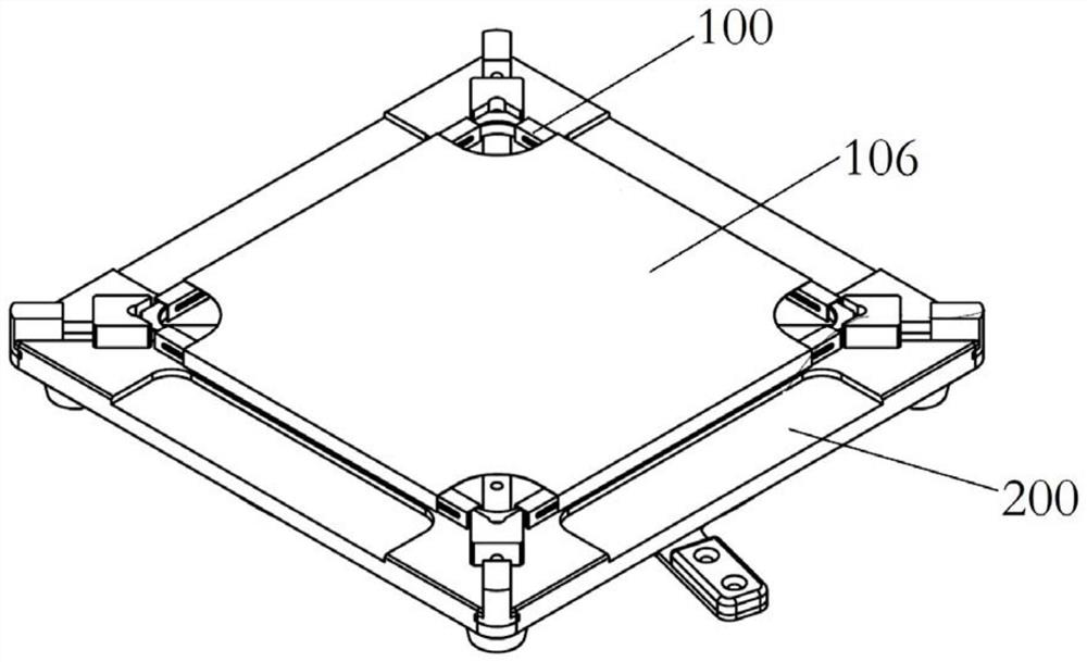
[0060] The flirtraine assembly provided in this embodiment, such as figure 1 As shown, the tensioning mechanism 200 and the banditer frame 100 are included; the tensioning mechanism 200 and the sliding frame 100 are used in conjunction, and the film 106 is disposed in the sliding frame in the process of the wafer. 100 on 100;

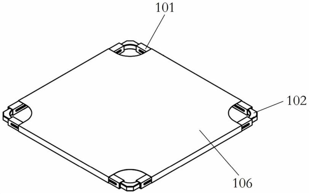
[0061] like figure 2 As shown, the sliding frame 100 has a rectangular shape, has a four-sliding film tube 101, and the four sluts 101 constitute the four sides of the stretch film 100, and the flungeon 101 has a cavity;

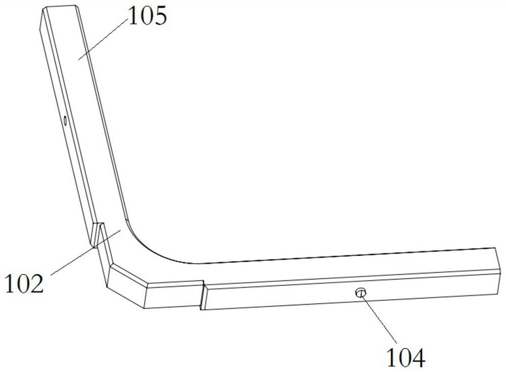
[0062] like image 3 As shown, the adjacent end slides in the adjacent end slide inserted with a tension angle 102, the tension angle 102 is "L" type, and the two ends are suitable for sliding to the sliding tube. Insert 105 in the cavity of 101;

[0063] like Figure 4 , 5 As shown, a finiterating device is provided between the tensioning angle 102 and the sliding tube 101; the limit device includes a limit slot 103 disposed on the side wa...

Embodiment 2

[0076] The flunter method according to the present embodiment, the flirtave assembly of Example 1, including the steps of:

[0077] The scratch film 106 is placed, and the four corners of the rectangular scrubbing film 106 are disconnected to avoid the position of the top block 205 on the base 201, and the cutting film 106 will be cut. The front surface of the base 201 is laid;

[0078] The slacete frame 100 is placed such that the second end 209 of the driving groove 207 on the turntable 206 is located at the position of the drive shaft 204, that is, the top tension block 205 is in the second state away from the center of the base 201; the sliding tube of the slope frame 100 The outer surface of 101 is pasted on the double-sided adhesive, press the tension angle 102, placed on the base 201, so that a tension angle 102 is in contact with a top block 205;

[0079] The mobile handle 210 causes the turntable 206 to rotate, so that the drive shaft 204 also moves, the drive shaft 204 i...


PUM


Abstract

The invention provides a tightening mechanism for wafer cleavage, a film tightening assembly and a film tightening method, and belongs to the technical field of cleavage. The tightening mechanism for wafer cleavage comprises: a base and four jacking blocks; the front surface of the base is used for placing a film tightening frame; the four jacking blocks are arranged at four corners of the front face of the base at intervals; the jacking blocks are arranged on the base in a driven and sliding mode; the jacking blocks have a first state of being close to the center of the base and also have a second state of being far away from the center of the base; and the jacking blocks are suitable for being propped against the film tightening frame. According to the tightening mechanism for wafer cleavage, the position and the shape of the film tightening frame are fixed through switching of the jacking blocks between the first state and the second state, and then a cutting-up film is bonded to the film tightening frame; and only one worker is needed to easily complete the process, manpower is saved, and the working efficiency is improved.

Description

Technical field [0001] The present invention relates to the technical field of a fractal device, and more particularly to a tensioning mechanism, a flirtraine assembly, and a flirtrane method for wafer decomposition. Background technique [0002] After the crystalline mineral is protected, the crystal is cracked in a certain crystallization direction of the crystal in a certain crystallization direction, referred to as a solution; the cleansing smooth plane is referred to as a decision. [0003] During the process of the solution, the wafer to be decompressed is required to be placed on the tubing film of the stretch frame, and the film has a certain tension to maintain the horizontal force of the semiconductor wafer. [0004] The tight process of the existing scrubbing film is handled by one or more workers, and the tie film is tightened and attached to the sliding film, so that the film is bonded to the sliding film; but in bonding During the process, multi-person auxiliary sli...

Claims


Application Information

Patent Timeline
IPC IPC(8): B28D5/00H01L21/67
CPCB28D5/00B28D5/0058B28D5/0082H01L21/67092H01L21/67132
Inventor 纪伟夏志伟任邵彬刘严庆
Owner 精良(北京)电子科技有限公司
Learn More