
Nanocone spectral analysis device and spectral analysis method

A technology of spectral analysis and nano-cone, which is applied in the field of spectroscopic detection and spectral analysis, to achieve the effect of avoiding structure and process flow and good light absorption ability

Active Publication Date: 2021-07-27
NANJING UNIV
View PDF2 Cites 0 Cited by
  • Summary
  • Abstract
  • Description
  • Claims
  • Application Information

AI Technical Summary

Problems solved by technology

[0004] The purpose of this invention is to solve the problem that the integration and resolution of traditional CCDs are close to the baseline, and it is difficult to make a breakthrough due to the limitation of light wave diffraction effect

Method used


Image

  • Nanocone spectral analysis device and spectral analysis method
  • Nanocone spectral analysis device and spectral analysis method
  • Nanocone spectral analysis device and spectral analysis method

Examples


Embodiment Construction

[0020] The present invention will be further explained below in conjunction with the accompanying drawings and specific embodiments.

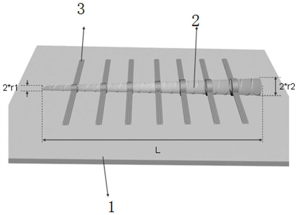
[0021] This embodiment provides a nanocone spectral analysis device, such as figure 1 As shown, it includes a substrate 1, a nanocone 2 placed flat on the substrate, and a group of electrodes 3 distributed on the nanocone; the top radius of the nanocone is recorded as r1, which is the radius of the incident light entrance port; nanometer The bottom radius of the frustum is denoted as r2, which is the bottom radius of the nano-cone, and the length of the nano-cone is denoted as L; the values ​​of the top radius length r1 and the bottom radius length r2 are within hundreds of nanometers, and the length L is several microns long , the length r1 of the top radius is at most one-half of the length r2 of the bottom radius. In this embodiment, r1=20nm, r2=100nm, L=2000nm.

[0022] The present embodiment provides the spectral analysis method of above...


PUM


Abstract

The invention discloses a nanocone spectrum analysis device which comprises a substrate, a nanocone platform horizontally placed on the substrate and a group of electrodes distributed on the nanocone platform. The top radius of the nano frustum is marked as r1 which is the radius of an incident port of incident light; the bottom radius of the nano frustum is marked as r2 which is the radius of the bottom end of the nano frustum, and the length of the nano frustum is marked as L; the top radius length r1 and the bottom radius length r2 are both within hundreds of nanometers, the length L is several micrometers, and the top radius length r1 is at most one half of the bottom radius length r2. Due to the fact that the structure of the silicon nanowire can restrain light with different wavelengths at different positions, the silicon nanowire has the light splitting capacity, the silicon nanowire has the good light absorption capacity, and the cavity mode color resolution capacity of the nanowire and the potential of on-line integrated wide spectrum detection are shown.

Description

technical field [0001] The invention provides a method for realizing spectroscopic detection and spectral analysis by using a nanocone device structure, and belongs to the technical field of semiconductor devices. Background technique [0002] In the traditional silicon process, in the charge-coupled device (CCD) color detection implementation mode, a filter array needs to be covered on the photosensitive layer to realize the selective recognition of the three primary colors of RGB. Mainly use the dichroic mirror array, that is, the traditional R, G, B filters, generally four filters form a group to form a pixel, this layer distinguishes the spectral colors, and transmits the light of different colors to the next In the CCD array of one layer, the bottom CCD array layer is mainly used for photosensitive, storage and transfer of photogenerated charges. Although its device performance has been breakthrough, but still subject to the structure of the traditional CCD. So far, i...

Claims


Application Information

Patent Timeline
Patent Type & Authority Applications(China)
IPC IPC(8): G01J3/12G01J3/28G01J3/42
CPCG01J3/12G01J3/28G01J3/42G01J2003/282
Inventor 王军转孙浚凯施毅
Owner NANJING UNIV
Learn More