


Quick Research
Generate reliable direction feasibility study reports for your R&D in just a few steps.

Technical Q&A
Discover and master advanced knowledge NOW. Basics, ideas, possibilities, all at once.

Find Solutions
As an expert in R&D theories, this can generate solutions to your technical problems instantly.

Evaluate Feasibility
Analyze your overall solution with one click, know your potential R&D risks in advance.

Monitor Landscape
Get weekly tech updates, stay abreast of the latest tech innovations and key insights.
Primary iron core structure of linear motor
A primary iron core and linear motor technology, applied in the direction of magnetic circuit shape/style/structure, electrical components, electromechanical devices, etc., can solve the problems affecting the performance of the motor, low mechanical strength of single-piece assembled linear motors, and cumulative errors. Achieve the effects of high manufacturing efficiency, easy automatic winding, and high slot fill rate
- Summary
- Abstract
- Description
- Claims
- Application Information
AI Technical Summary
Problems solved by technology
Method used
Image

Examples
Embodiment 1
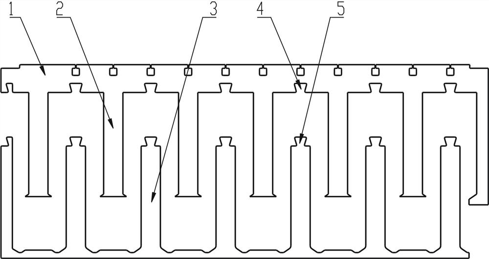
[0017] Such as figure 1 As shown, the primary iron core structure of a linear motor of the present invention is composed of primary yoke 1, fixed teeth 2, and nested teeth 3. The fixed teeth 2 and nested teeth 3 are arranged alternately to form the primary teeth of the present invention. The fixed teeth 2 are evenly arranged on the primary yoke 1 and integrated with the primary yoke 1 . The primary yoke 1 is provided with a slot 4 between every two fixed teeth 2 . The root of each nesting tooth 3 is provided with a convex key 5 matched with the slot 4, and the nesting teeth 3 are sequentially connected at the top to form a whole.
[0018] Before installation, the overall structure composed of the fixed teeth 2 and the nested teeth 3 is automatically wound. After the winding is completed, the convex keys 5 of each nested tooth 3 correspond to the slots 4 and are pushed into the slots. 4, the nested teeth 3 are installed on the primary yoke 1 to form a primary iron core structu...
Embodiment 2
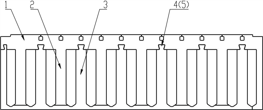
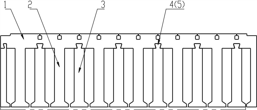
[0022] Such as Figure 4 As shown, this embodiment is composed of a primary yoke 1, fixed teeth 2, and nested teeth 3, and the fixed teeth 2 and nested teeth 3 are arranged alternately to form the primary teeth of the present invention. The fixed teeth 2 are evenly arranged on the primary yoke 1 and are integrated with the primary yoke 1 . The primary yoke 1 is provided with a slot 4 between every two fixed teeth 2 . The root of each nested tooth 3 is provided with a protruding key 5 matching with the slot 4 .
[0023] Before installation, the overall structure composed of fixed teeth 2 and each nested tooth 3 are automatically wound. After the winding is completed, each nested tooth 3 is installed on the primary yoke 1 in turn, and an open groove can be formed according to the tooth shape structure. Or the primary iron core structure of the semi-closed slot. In order to facilitate installation and achieve sufficient positioning, the slot 4 is a dovetail slot structure. Afte...
PUM
 Abstract
Description
Claims
Application Information
 - R&D Engineer
- R&D Manager
- IP Professional
- Industry Leading Data Capabilities
- Powerful AI technology
- Patent DNA Extraction
Browse by: Latest US Patents, China's latest patents, Technical Efficacy Thesaurus, Application Domain, Technology Topic, Popular Technical Reports.
© 2024 PatSnap. All rights reserved.Legal|Privacy policy|Modern Slavery Act Transparency Statement|Sitemap|About US| Contact US: help@patsnap.com