Oily sludge treatment system and method

A technology of sludge treatment and sludge, applied in the field of heating and distillation separation of materials, can solve the problems of low efficiency of treatment methods, large environmental pollution, secondary pollution, etc., and achieve improved energy utilization, low operating costs, and harmless treatment Effect

Pending Publication Date: 2021-07-23
SICHUAN JUNHE ENVIRONMENTAL PROTECTION
View PDF6 Cites 3 Cited by
  • Summary
  • Abstract
  • Description
  • Claims
  • Application Information

AI Technical Summary

Problems solved by technology

[0005] The technical problem to be solved and the technical task proposed by the present invention are to improve the existing technology and provide an oily sludge treatment system to solve the problem of low efficiency, high cost and easy secondary pollution of the oily sludge treatment method in the current technology , great environmental pollution and poor applicability

Method used


Image

  • Oily sludge treatment system and method
  • Oily sludge treatment system and method
  • Oily sludge treatment system and method

Examples


Embodiment 1

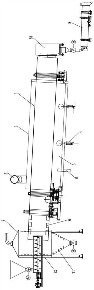
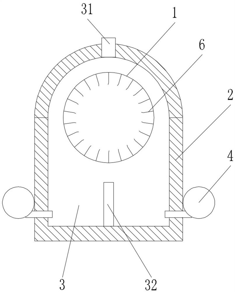
[0055] Such as Figure 1 to Figure 12 As shown, an oily sludge treatment system mainly includes an anaerobic distillation system and a condensation separation system. The anaerobic distillation system includes a rotary drum 1 and a casing 2 surrounding the peripheral periphery of the rotary drum 1. The casing 2 and the rotary drum There is a space between 1 to form a heating chamber 3. The heating chamber 3 surrounds the circumference of the rotary drum 1. A heating system is arranged on the heating chamber 3. The heating system adopts fuel combustion for heating. The rotary drum 1 is a cylinder with openings at both ends, which is driven by a motor assembly to rotate around its axis, and the casing 2 is placed statically, that is, the rotary cylinder 1 rotates relative to the casing 2 inside the casing 2, and the rotary cylinder 1 In the axial direction, sealing mechanisms are respectively provided between the two ends of the casing 2 and the rotating cylinder 1, there is a r...

Embodiment 2

[0084]The difference from Embodiment 1 is that both the condenser and the slag cooling device of the condensation separation system use water as the cooling medium, and the water absorbs the heat of the distillation gas at the condenser and the temperature rises. At the same time, the water in the slag The cooling device absorbs the heat of the sludge and the temperature rises. The heated water is usually sent to the cooling tower to cool down and then circulated to the condenser and the slag cooling device for use. This method wastes heat. Here, the gas-liquid The heat exchange device is to pass the heated water into the gas-liquid heat exchange device to preheat the combustion-supporting gas and non-condensable gas to improve the sufficient rate of heat utilization. The device is preheated by the heated water, and then the combustion gas and non-condensable gas are preheated by the flue gas through the heat exchanger, making full use of heat, improving energy utilization effi...


PUM


Abstract

The invention discloses an oily sludge treatment system which comprises an anaerobic distillation system and a condensation separation system, the anaerobic distillation system comprises a rotary cylinder and a shell surrounding the circumferential periphery of the rotary cylinder, a heating cavity is formed between the shell and the rotary cylinder, a heating system is arranged on the heating cavity, oily sludge is heated in the rotary cylinder to be subjected to anaerobic distillation, distillation gas generated by anaerobic distillation is conveyed to a condensation separation system to be subjected to condensation separation to obtain non-condensable gas, liquid oil and waste water, the non-condensable gas and the liquid oil serve as fuel to be supplied to the heating system, and the non-condensable gas and combustion-supporting gas pass through a heat exchanger, are preheated by smoke generated by combustion and then are conveyed to the heating system. Water and petroleum hydrocarbons in the oily sludge are distilled and separated in an oxygen-free environment, substances only change physically and do not change chemically, heating power consumption is low, non-condensable gas and liquid oil are recycled as fuel to be utilized, self-sufficiency is achieved, the operation cost is low, secondary pollution is avoided, and harmless treatment is achieved.

Description

technical field [0001] The invention relates to the technical field of using a rotary kiln device to heat, distill and separate materials in an oxygen-free environment, and in particular to an oily sludge treatment system and method. Background technique [0002] The waste drilling mud produced by preparing drilling mud with mineral oil as the continuous phase for natural gas extraction is the oily solid waste (referred to as oily sludge) produced by mixing the oily mud with the drilling fluid added during oil and gas production. Included in the "National Hazardous Waste List" waste category HW08 waste mineral oil and waste containing mineral oil, waste code 072-001-08, hazardous characteristic is toxicity (T), which mainly contains oil, water, rock debris and other substances, with complex composition It is difficult to directly process and utilize, and as a hazardous waste, simple landfill or random discharge is prohibited. China's oil shale gas resources are very rich. E...

Claims


Application Information

Patent Timeline
Patent Type & Authority Applications(China)
IPC IPC(8): C02F11/13F23G7/06C02F101/32
CPCC02F11/13F23G7/06C02F2101/32
Inventor 李乐军罗启贵邓俊
Owner SICHUAN JUNHE ENVIRONMENTAL PROTECTION
Why Eureka
Try Eureka