
Gas leakage detection alarm

A leakage detection and alarm technology, applied in the direction of alarms, instruments, chemical instruments and methods, etc., can solve the problems of insufficient air and oxygen, explosion, gas leakage, etc., and achieve the effect of convenient operation

Active Publication Date: 2021-07-20
INNER MONGOLIA WANRUI NATURAL GAS CO LTD
View PDF9 Cites 1 Cited by
  • Summary
  • Abstract
  • Description
  • Claims
  • Application Information

AI Technical Summary

Problems solved by technology

[0003] At present, when the gas leaks, when the content in the air reaches a certain level, the oxygen in the air will be insufficient, which will cause people to suffocate, and when the natural gas accumulates in a closed environment such as a house or a tent, when it reaches a certain proportion, It will trigger a powerful explosion, and it is necessary to use a detection alarm for detection and processing to avoid greater harm from gas leakage. Therefore, it is urgent to set up a gas leakage detection alarm to solve such problems

Method used


Image

  • Gas leakage detection alarm
  • Gas leakage detection alarm
  • Gas leakage detection alarm

Examples


Embodiment 1

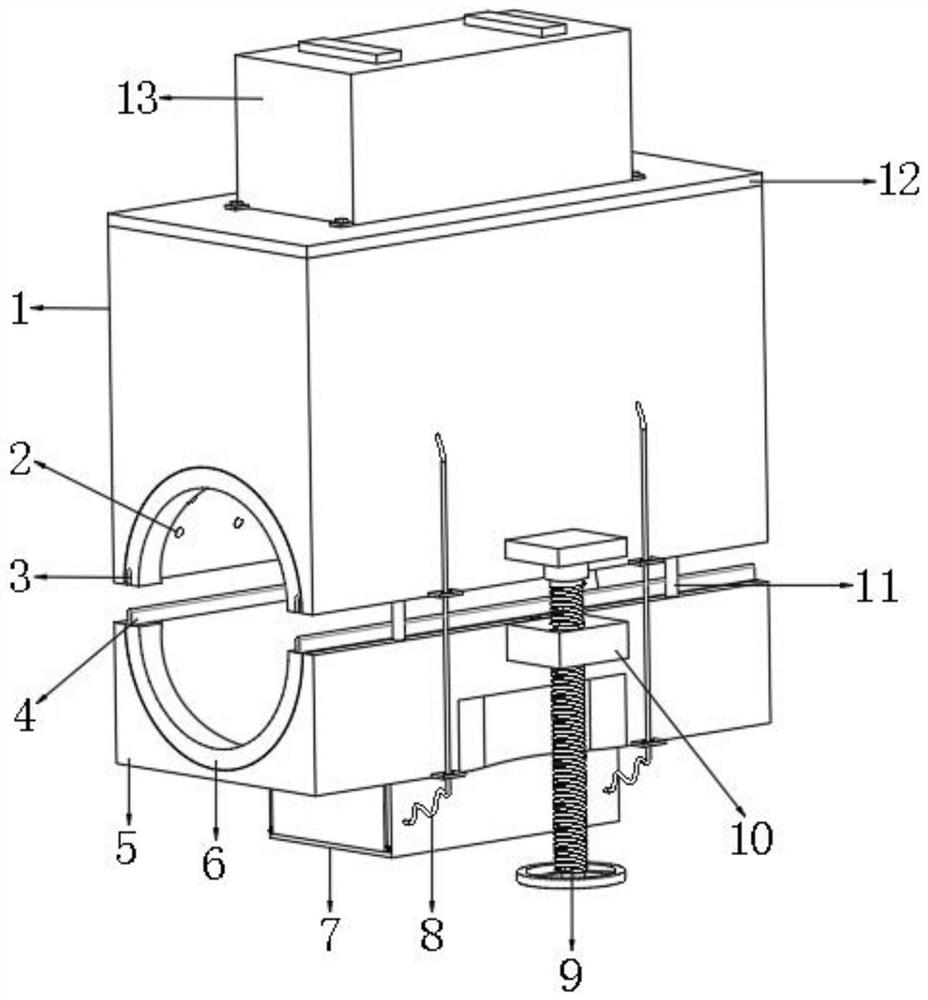
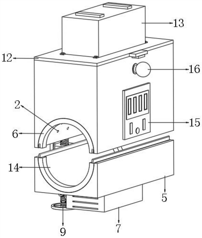
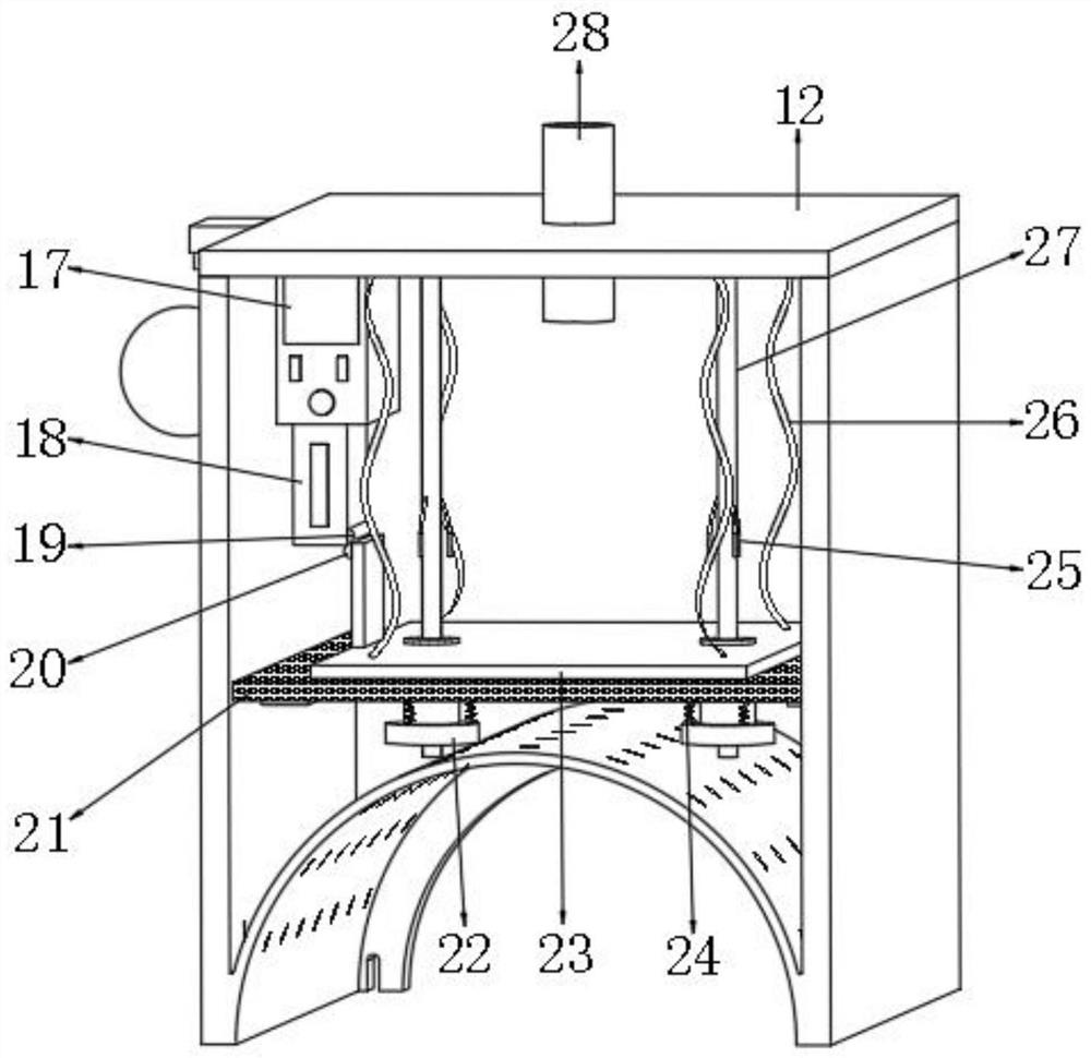
[0032] A gas leak detection alarm, such as Figure 1-6 As shown, the detection box 1 is included, the bottom of the detection box 1 is provided with a base 5, and a connection structure is arranged between the top of one side of the base 5 and the bottom of one side of the detection box 1, and the top of the base 5 and the bottom of the detection box 1 are both There is a semicircular clamping groove 14, and there are multiple rows of air holes 2 equidistantly distributed between the bottom inner wall and the bottom outer wall of the test box 1, and support blocks 29 are welded on both inner walls of the test box 1 near the bottom , and the top of the support block 29 is placed with a sealing foam board 21, the middle position of the sealing foam board 21 is bonded with a pusher plate 23, and the inner wall of one side of the detection box 1 is connected with the main control machine 17 by bolts, and the main control machine 17 The bottom is connected with a pressure sensor 18...

Embodiment 2

[0041] A gas leak detection alarm, such as Figure 7 As shown, in order to solve the problem of gas removal; this embodiment makes the following improvements on the basis of embodiment 1: the turbid aqueous solution 30 is replaced by an ammonia solution 33, and the concentration of the ammonia solution 33 is 24%-28%.

[0042] When this embodiment is in use, the leaked gas can enter the ammonia solution 33 through the gas distribution pipe 31. After the ammonia solution 33 contacts the gas, a chemical reaction will occur and a strong odor will be produced. If the alarm 16 works In case of abnormality, the alarm operation of gas leakage can be carried out through the odor, forming the performance of multi-level alarm.


PUM


Abstract

The invention discloses a gas leakage detection alarm. The gas leakage detection alarm comprises a detection box, a base is arranged at the bottom of the detection box, a connecting structure is arranged between the top of one side of the base and the bottom of one side of the detection box, and semicircular clamping grooves are formed in the top of the base and the bottom of the detection box correspondingly; a plurality of rows of air holes distributed at equal intervals are formed between the inner wall and the outer wall of the bottom of the detection box, supporting blocks are fixedly connected to the inner walls of the two sides, close to the bottom, of the detection box, a sealing foam plate is placed on the tops of the supporting blocks, and a pushing plate is bonded to the middle of the sealing foam plate. The pressure intensity in the detection box is increased, a pushing plate and a sealing foam plate are pushed to rise, a pressure piece makes contact with a stress piece, a pressure sensor bears pressure, gas leakage alarm processing is conducted through a main control computer and an alarm, operation is convenient, gas can be absorbed through a turbid water solution, and leaked gas is prevented from being directly discharged around a detection environment.

Description

technical field [0001] The present invention relates to the technical field of gas detection, in particular to a gas leakage detection and alarm device. Background technique [0002] Gas is the general term for gaseous fuel, which can be burned to release heat for use by residents and industrial enterprises. There are many types of gas, mainly natural gas, artificial gas, liquefied petroleum gas, biogas, and coal gas. Natural gas is one of the main energy sources in people's daily life, and it provides residents with living heat, but natural gas also has certain hazards, especially in the case of leakage. [0003] At present, when the gas leaks, when the content in the air reaches a certain level, the oxygen in the air will be insufficient, which will cause people to suffocate, and when the natural gas accumulates in a closed environment such as a house or a tent, when it reaches a certain proportion, A powerful explosion will be triggered, and a detection alarm needs to b...

Claims


Application Information

Patent Timeline
Patent Type & Authority Applications(China)
IPC IPC(8): G08B21/16B01D53/18B01D53/14
CPCG08B21/16B01D53/18B01D53/14B01D53/1487
Inventor 梁坤
Owner INNER MONGOLIA WANRUI NATURAL GAS CO LTD
Learn More