
Circuit and method for reducing standby power consumption

A circuit and self-locking circuit technology, which is applied in the direction of output power conversion devices, electrical components, high-efficiency power electronic conversion, etc., can solve the problem of high standby power consumption of electronic devices, and achieve the effect of low hardware consumption

Pending Publication Date: 2021-07-16
代傲阿扣基金两合公司
View PDF0 Cites 0 Cited by
  • Summary
  • Abstract
  • Description
  • Claims
  • Application Information

AI Technical Summary

Problems solved by technology

[0004] One of the objectives of the present invention is to provide a power control circuit and method for reducing standby power consumption for the problem of high standby power consumption of electronic devices

Method used


Image

  • Circuit and method for reducing standby power consumption
  • Circuit and method for reducing standby power consumption

Examples


Embodiment Construction

[0015] In order to make the object, technical solution and advantages of the present invention clearer, the present invention will be further described in detail below in conjunction with the accompanying drawings and embodiments. It should be understood that the specific embodiments described here are only used to explain the present invention, and are not intended to limit the present invention.

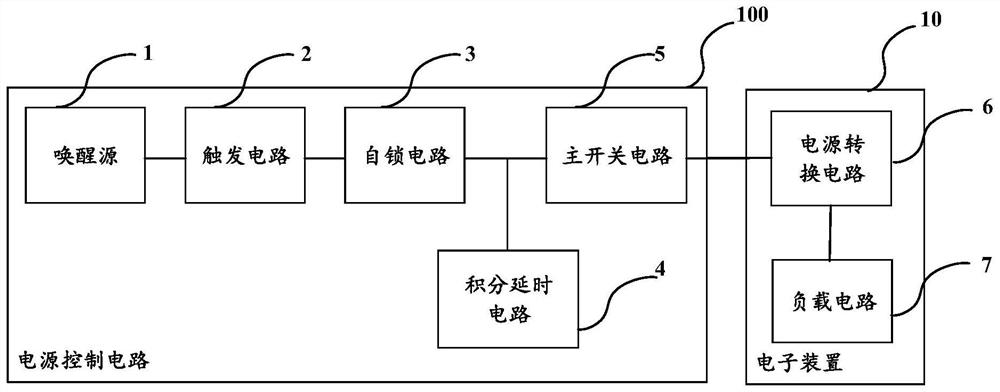
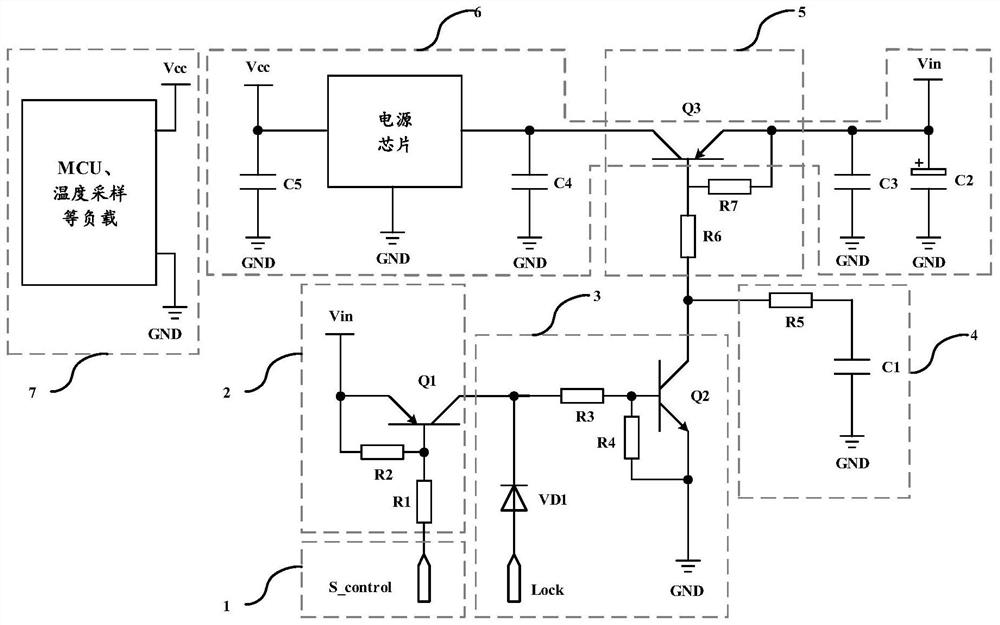
[0016] figure 1 A power supply control circuit 100 according to an embodiment of the present disclosure is schematically shown. Such as figure 1 As shown, the power control circuit 100 can be coupled to the power conversion circuit 6 for supplying power to the electronic device 10, so as to completely shut down the power conversion circuit 6 in the standby state, and turn on the power in response to the control signal indicating to enter the startup state. The conversion circuit 6 and then keeps the power conversion circuit 6 in the on state. The standby state refers to a state ...


PUM


Abstract

The invention relates to a circuit and a method for reducing standby power consumption, and provides a power supply control circuit, which is coupled to a power supply conversion circuit for powering an electronic device so as to fully turn off the power supply conversion circuit in a standby state and enter a starting state to turn on the power supply conversion circuit and then hold the power supply conversion circuit in an on state in response to a control signal indication, and comprises a main switch circuit, a trigger circuit and a self-locking circuit, wherein the main switch circuit is coupled to the power supply conversion circuit and used for switching on the power supply conversion circuit when being switched on and switching off the power supply conversion circuit when being switched off, the trigger circuit receives the control signal and is used for responding to the control signal to indicate to enter a starting state so as to trigger the self-locking circuit, and the self-locking circuit is coupled to the main switching circuit and is used for switching on the main switching circuit in response to triggering of the trigger circuit and keeping the main switching circuit in a switching-on state.

Description

technical field [0001] The present disclosure relates to circuits and methods for reducing standby power consumption, and more particularly to power control circuits and methods for reducing standby power consumption. Background technique [0002] As the energy efficiency standards for electronic devices (such as household appliances) become higher and higher, people pay more and more attention to the standby power consumption of electronic devices. [0003] Taking the washing machine as an example, in the standby mode, the power board of the washing machine, the temperature sampling circuit in the display board, MCU (Microcontroller Unit, micro control unit), power chip, etc. will continue to consume electric energy due to the power supply not being cut off, thus increasing the standby time. power consumption. At present, the main method to reduce the standby power consumption of household appliances is to use a power chip and MCU with lower quiescent current or to reduce ...

Claims


Application Information

Patent Timeline
Patent Type & Authority Applications(China)
IPC IPC(8): H02M1/00
CPCH02M1/00Y02B70/10
Inventor 董文明左厚贝李达陈鹏
Owner 代傲阿扣基金两合公司
Learn More