
Automatic particle counting device for particle materials

A technology for counting devices and granular materials, which is applied in the field of automatic counting devices for granular materials, which can solve the problems of limited size, large space occupation, failure to identify damaged pieces or half pieces, etc., to ensure the yield rate, improve accuracy and reliability Effect

Active Publication Date: 2021-07-16
SHANDONG SMA PHARMATECH CO LTD
View PDF12 Cites 0 Cited by
  • Summary
  • Abstract
  • Description
  • Claims
  • Application Information

AI Technical Summary

Problems solved by technology

[0003] Traditional capsule microchip filling or counting machines mostly use sensors such as optical fibers to count grains or indirectly count grains through sideline weighing machines. Devices that use sensors such as optical fibers to count grains online occupy a large space and can only Counting one grain at a time limits the size of the granules and tablet feeding channels, and is easy to block, which affects production efficiency. The method of indirect counting with a weighing machine can only be weighed at the sideline to obtain an approximate number of grains or directly Compare the weight to determine whether the quantity in the capsule or medicine bottle is qualified, and the above two methods cannot identify the material of the damaged tablet or half tablet, resulting in invalid tablets or tablets with poor effect that affect the drug release effect flowing to the finished product channel

Method used


Image

  • Automatic particle counting device for particle materials
  • Automatic particle counting device for particle materials
  • Automatic particle counting device for particle materials

Examples


Embodiment Construction

[0022] The specific implementation manners of the present invention will be further described in detail below in conjunction with the accompanying drawings and embodiments. The following examples are used to illustrate the present invention, but are not intended to limit the scope of the present invention.

[0023] In the description of this application, it is to be understood that the terms "center", "upper", "lower", "front", "rear", "left", "right", "vertical", "horizontal", The orientations or positional relationships indicated by "top", "bottom", "inner", "outer", etc. are based on the orientations or positional relationships shown in the drawings, and are only for the convenience of describing the application and simplifying the description, rather than indicating or implying References to devices or elements must have a particular orientation, be constructed, and operate in a particular orientation and therefore should not be construed as limiting the application. In t...


PUM


Abstract

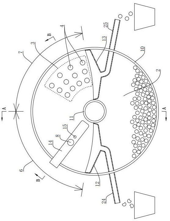
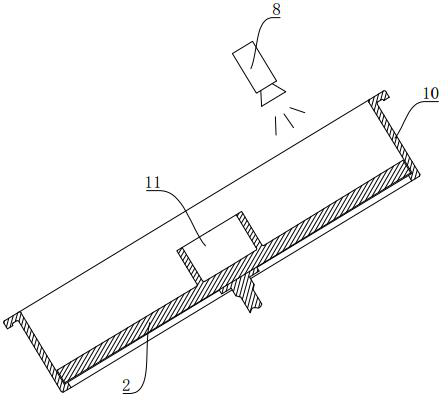
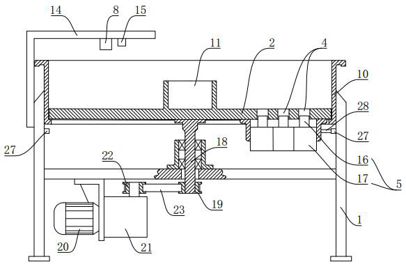
The invention discloses an automatic particle counting device for particle materials. The device comprises a rack, a rotating tray driven by a power device is mounted on the rack, a plurality of single particle holes are formed in a material carrying area of the rotating tray, and an ejection device is arranged at the bottom of each single particle hole; a defective product unloading area and a finished product unloading area are arranged at the left side and the right side of the rotating tray on the rack respectively, a camera used for collecting images of the material carrying area is installed at the position, over the defective product unloading area, of the rack, and the signal output end of the camera and the control ends of the ejection devices are both electrically connected with a controller; and the controller receives image information of the camera in real time and compares the image information with standard image information to judge whether particles in the single particle holes are intact or not so as to control the ejection devices to act in the defective product unloading area or the finished product unloading area. The device can accurately meter the quantity of output particles, can effectively identify and separate unqualified invalid tablets such as half tablets and broken tablets, and has the advantages of high particle counting speed and high yield.

Description

technical field [0001] The invention relates to an automatic counting device for granular materials. Background technique [0002] In the production and packaging process of granular drugs (such as capsules, tablets, etc.), it is necessary to accurately measure the number of particles to meet the requirements of quantitative packaging of drugs, which requires the use of capsule microtablet filling or counting machines. [0003] Traditional capsule microchip filling or counting machines mostly use sensors such as optical fibers to count grains or indirectly count grains through sideline weighing machines. Devices that use sensors such as optical fibers to count grains online occupy a large space and can only Counting one grain at a time limits the size of the granules and tablet feeding channels, and is easy to block, which affects production efficiency. The method of indirect counting with a weighing machine can only be weighed at the sideline to obtain an approximate number...

Claims


Application Information

Patent Timeline
Patent Type & Authority Applications(China)
IPC IPC(8): B07C5/02B07C5/342B07C5/34B07C5/36B07C5/38
CPCB07C5/02B07C5/342B07C5/34B07C5/362B07C5/38
Inventor 殷文平王阳王斌董海洲张宇王辉
Owner SHANDONG SMA PHARMATECH CO LTD
Learn More