Wind driven generator with automatic protection function

A technology for automatic protection of wind power generators, applied in wind power generators, power storage wind power generators, control of wind power generators, etc., can solve problems such as increased working strength of generators, damage to generators, lack of protection measures, etc.

Inactive Publication Date: 2021-07-13
杭州科斐新材料有限公司
View PDF0 Cites 0 Cited by
  • Summary
  • Abstract
  • Description
  • Claims
  • Application Information

AI Technical Summary

Problems solved by technology

In recent years, due to the gradual depletion of traditional energy sources and the increasingly serious environmental pollution problems, wind energy has gradually attracted people's attention as a clean energy source. Like other hydraulic and thermal power generation machinery, wind power generators play an important role in the development of productivity as a power source instead of manpower. , in the process of using wind turbines, in order to make better use of wind energy effectively, it is necessary to adjust the wind blades to the most suitable height, but most of the existing wind turbines cannot be adjusted in height, and the existing During the power generation process of the wind turbine, there is no corresponding protective measure in case of strong wind. In this case, the speed of the wind blade will be too fast under the action of strong wind, and the speed of the wind blade will increase the working strength of the generator, which will easily cause the generator damage

Method used


Image

  • Wind driven generator with automatic protection function
  • Wind driven generator with automatic protection function
  • Wind driven generator with automatic protection function

Examples


Embodiment Construction

[0033] The following will clearly and completely describe the technical solutions in the embodiments of the present invention with reference to the accompanying drawings in the embodiments of the present invention. Obviously, the described embodiments are only some, not all, embodiments of the present invention. Based on the embodiments of the present invention, all other embodiments obtained by persons of ordinary skill in the art without making creative efforts belong to the protection scope of the present invention.

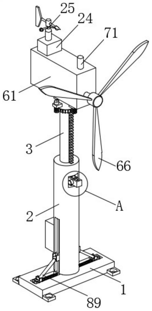
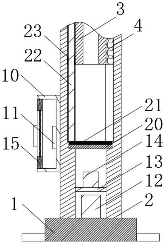
[0034] see Figure 1-7, the present invention provides a technical solution: a wind power generator with an automatic protection function, including a base plate 1, a power generation component 6, a protection component 7, a support component 8 and an angle adjustment component 9;

[0035] Bottom plate 1: The support barrel 2 is fixed on the upper side, the upper end of the support barrel 2 is slidably connected with the sliding pipe 3, the circumferential sur...


PUM


Abstract

The invention discloses a wind driven generator with an automatic protection function. The wind driven generator comprises a bottom plate, a power generation assembly, a protective assembly, a supporting assembly and an angle adjusting assembly, wherein the bottom plate is designed in such as way that: a supporting barrel is fixed to the upper side surface of the bottom plate, a sliding pipe is slidably connected to the upper end of the interior of the supporting barrel, a rack is fixed to the circumferential surface of the sliding pipe, and a mounting barrel is rotationally connected to the upper end surface of the sliding pipe; and the power generation assembly is designed in such as way that: the power generation assembly comprises a mounting box, a power generator, a reduction gearbox, a rotating shaft, a connecting disc and fan blades, the mounting box is fixed to the upper end surface of the mounting barrel, the power generator is mounted at the left end in the mounting box, an input shaft of the power generator is connected with an output shaft of the reduction gearbox, and the reduction gearbox is mounted at the middle part of the lower side wall in the mounting box, and a through hole is formed in the front side surface of the mounting box, so that a height can be adjusted very conveniently, and a rotating speed of the fan blades can be reduced when wind power is too large.

Description

technical field [0001] The invention relates to the technical field of wind power generators, in particular to a wind power generator with an automatic protection function. Background technique [0002] Wind energy was the most important power source before the invention of the steam engine. Thousands of years ago, sailboats were used for transportation, and later windmills were used for grinding flour and pumping water. In recent years, due to the gradual depletion of traditional energy sources and the increasingly serious environmental pollution problems, wind energy has gradually attracted people's attention as a clean energy source. Like other hydraulic and thermal power generation machinery, wind power generators play an important role in the development of productivity as a power source instead of manpower. , in the process of using wind turbines, in order to make better use of wind energy effectively, it is necessary to adjust the wind blades to the most suitable heig...

Claims


Application Information

Patent Timeline
IPC IPC(8): F03D9/11F03D13/20F03D7/02F03D7/04
CPCF03D7/0204F03D7/0276F03D7/042F05B2270/1011F05B2270/32F05B2270/321F05B2270/602F03D9/11F03D13/20Y02E10/72Y02E10/728Y02E70/30
Inventor 杨仲暴唐修明
Owner 杭州科斐新材料有限公司
Why Eureka
Try Eureka