
Continuous stamping and punching die for plates

A plate and mold technology, applied in the field of continuous stamping and punching dies for plates, can solve the problems of low efficiency and low precision of plates, and achieve the effect of improving punching precision and efficiency

Inactive Publication Date: 2021-07-13
HEFEI ZHENGTE MACHINERY CO LTD
View PDF5 Cites 2 Cited by
  • Summary
  • Abstract
  • Description
  • Claims
  • Application Information

AI Technical Summary

Problems solved by technology

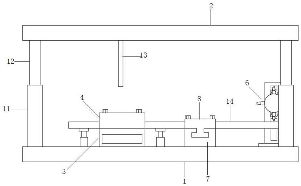
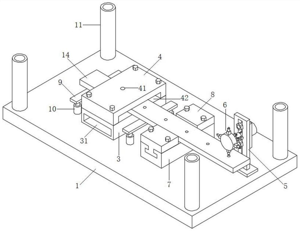
[0004] The object of the present invention is to provide a continuous stamping and punching die for plates. A drive device is fixedly connected to the lower die, and the drive device drives the plates to move, and the plates move at the same distance each time, which solves the problem of low efficiency of the existing manual movement of the plates. The problem of low precision

Method used


Image

  • Continuous stamping and punching die for plates
  • Continuous stamping and punching die for plates
  • Continuous stamping and punching die for plates

Examples


Embodiment Construction

[0028] The following will clearly and completely describe the technical solutions in the embodiments of the present invention with reference to the accompanying drawings in the embodiments of the present invention. Obviously, the described embodiments are only some, not all, embodiments of the present invention. Based on the embodiments of the present invention, all other embodiments obtained by persons of ordinary skill in the art without creative efforts fall within the protection scope of the present invention.

[0029] In the description of the present invention, it should be understood that the terms "through hole", "outlet hole", "bottom", "both sides", "top", "middle", "length", "inner", "four corners" ” and other indications of orientation or positional relationship are only for the convenience of describing the present invention and simplifying the description, rather than indicating or implying that the components or elements referred to must have a specific orientati...


PUM


Abstract

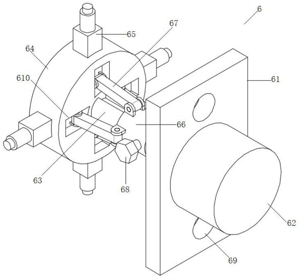
The invention discloses a continuous stamping and punching die for plates, and relates to the technical field of stamping dies. The continuous stamping and punching die comprises a lower die and an upper die, a punching base is fixedly connected to the lower die, a punching table is fixedly connected to the punching base, a channel for the plates to penetrate through is arranged between the punching base and the punching table, a through hole is formed in the punching table, and a punching rod is fixedly connected to the lower surface of the upper die; the lower die is fixedly connected with a vertical plate, and the vertical plate is fixedly connected with a driving device used for driving the plates to move; the driving device comprises a connecting plate, a motor is fixedly connected to the connecting plate, a rotating shaft is fixedly connected to the motor, a rotating disc is fixedly connected to the end of the rotating shaft, and a plurality of driving rods are evenly arranged on the circumferential side face of the rotating disc. The driving device is arranged on the lower die and can automatically drive the plates to move, so that the punching efficiency of the plates is improved, the punching precision of the plates is improved, and it is guaranteed that the distances between adjacent holes are the same.

Description

technical field [0001] The invention belongs to the technical field of automatic stamping, in particular to a continuous stamping and punching die for plates. Background technique [0002] At present, in the mold design stage in the early stage of project development, when the mold design manufacturer designs the outer cover (such as the inner panel of the back door of a certain model, there are many installation holes, and the punching directions of the holes are inconsistent), the number of mold processes cannot be completely To fully reflect the shape of the workpiece, a separate punching die is often added. Punching refers to punching various graphics on steel plates, leather, cloth, wood and other materials to meet different needs. The commonly used ones are punching. Hole mold, punching mold is a mold that can process dense small holes on a thin plate. This kind of mold is mainly used for the production of metal sheet screens and front and rear mesh doors of server cab...

Claims


Application Information

Patent Timeline
Patent Type & Authority Applications(China)
IPC IPC(8): B21D28/26B21D28/34B21D43/04
CPCB21D28/26B21D28/34B21D43/04
Inventor 孙健
Owner HEFEI ZHENGTE MACHINERY CO LTD
Learn More