Method and device for calculating rotor position of surface-mounted permanent magnet synchronous motor based on sliding mode observer
A technology of permanent magnet synchronous motor and sliding mode observer, which is used in the control of electromechanical transmission, control of generator, transportation and packaging, etc. and other problems, to achieve the effect of enhancing the anti-rotational speed disturbance capability, weakening the high-frequency chattering of the system, and eliminating the change of the system bandwidth.
Active Publication Date: 2022-05-31
WUXI WEIFU HIGH TECH CO LTD
View PDF4 Cites 0 Cited by
- Summary
- Abstract
- Description
- Claims
- Application Information
AI Technical Summary
Problems solved by technology
However, the sliding mode observer control is a discontinuous control. The unideality of the switch and the inertia of the system will cause high-frequency chattering in the system, which greatly reduces the accuracy of rotor position estimation.
In addition, the speed change will affect the amplitude of the back electromotive force, thereby affecting the system bandwidth, reducing the anti-speed disturbance ability of fixed parameters, and affecting the observation accuracy
Method used
View moreImage
Smart ImageViewing Examples
Examples
Embodiment Construction
[0057]
[0059]
[0062]
[0064]
[0067]
[0069]
[0070] Then,
[0071]
[0075]
[0076]
[0077]
[0082]
[0085]
[0086]
Login to View More PUM
 Abstract
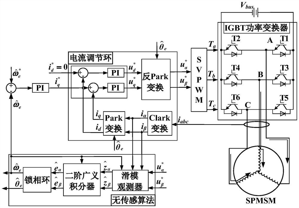
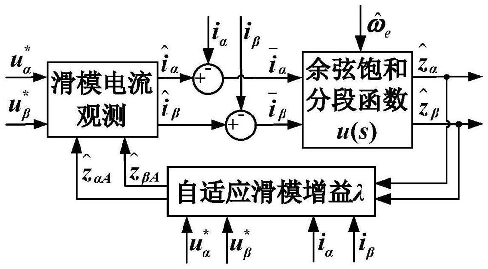
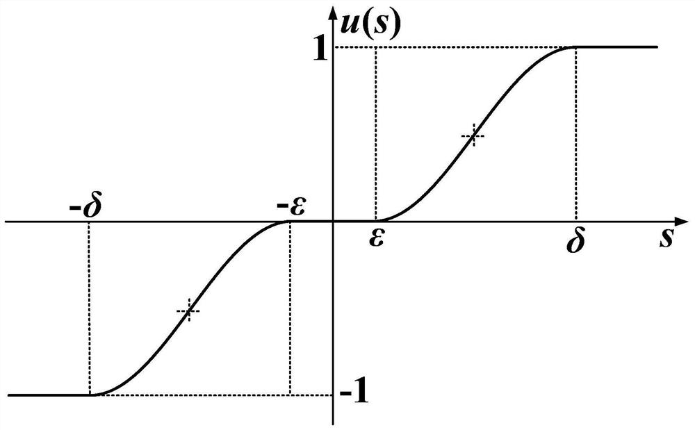
The invention provides a method and device for calculating the rotor position of a surface-mounted permanent magnet synchronous motor based on a sliding mode observer, which introduces the cosine saturation segmental function of the adaptive boundary layer thickness into the sliding mode control rate, and combines the quasi-unitary algorithm , effectively reduce high-frequency chattering and improve the calculation accuracy of rotor position and speed; firstly, according to the reference value of stator voltage, the actual value of stator current and the observed value of rotor electrical angular velocity, the standard unit value of back electromotive force sliding mode observation standard unit is calculated by sliding mode observer ; and then according to the back EMF sliding mode observation standard unit value and the rotor electrical angular velocity observation value through the second order generalized integrator to calculate the back electromotive force observation standard unit value; finally according to the back electromotive force observation standard unit value through the phase-locked loop calculation to obtain the rotor Electric angular velocity observation value and rotor electric angle observation value; the rotor position calculation method proposed by the present invention has high reliability and strong robustness, and meets the requirements of high-speed hydrogen pump, air compressor and other permanent magnet synchronous motor driving fields on system reliability and efficiency. requirements.
Description
Rotor position calculation method of surface-mounted permanent magnet synchronous motor based on sliding mode observer and device technical field The present invention relates to motor control technical field, especially a kind of permanent magnet synchronous motor rotor based on sliding mode observer Location calculation method. Background technique Permanent magnet synchronous motor has the characteristics of high power density, high efficiency, compact structure and high reliability. Fields such as wind power generation, household appliances and electric vehicles have been widely used. In order to realize the high-performance control of permanent magnet synchronous motor To meet the precise control of speed and current, the motor drive system must accurately obtain the rotor position in real time. The mechanical sensors of traditional direct position detection mainly include resolvers, encoders, Hall sensors, etc. It increases the cost of the motor, increases...
Claims
Login to View More Application Information
Patent Timeline
 Patent Type & Authority Patents(China)
IPC IPC(8): H02P21/18
CPCH02P21/18H02P2203/03H02P2207/05Y02T10/72
Inventor 袁晓强张清林李鸿怀蔡杰周海森皇甫雨欣
Owner WUXI WEIFU HIGH TECH CO LTD
Features
- R&D
- Intellectual Property
- Life Sciences
- Materials
- Tech Scout
- Unparalleled Data Quality
- Higher Quality Content
- 60% Fewer Hallucinations
Learn More Browse by: Latest US Patents, China's latest patents, Technical Efficacy Thesaurus, Application Domain, Technology Topic, Popular Technical Reports.
© 2025 PatSnap. All rights reserved.Legal|Privacy policy|Modern Slavery Act Transparency Statement|Sitemap|About US| Contact US: help@patsnap.com


