Low-voltage power line fault detection positioning system and fault detection method

A low-voltage power line and fault detection technology, which is applied in the direction of fault location, information technology support system, and fault detection according to conductor type, can solve the problems of affecting work efficiency, waste of low-voltage power lines, and low detection efficiency, so as to facilitate maintenance work and improve The effect of work efficiency

Pending Publication Date: 2021-07-09
山东卓文信息科技有限公司
View PDF7 Cites 0 Cited by
  • Summary
  • Abstract
  • Description
  • Claims
  • Application Information

AI Technical Summary

Problems solved by technology

Compared with low-voltage overhead lines and low-voltage overhead insulated lines, although low-voltage cable lines are more expensive and difficult to lay and maintain, they are reliable in operation, do not erect poles, do not occupy the ground, are not unsightly, and are less affected by the outside world. characteristics, and are widely used in low-voltage power distribution systems; however, low-voltage power lines are easily affected by voltage, such as excessive voltage, low voltage, or grounding of low-pressure lines will cause power lines to be faulty, thereby affecting work efficiency; therefore, the invention It is particularly important to develop a low-voltage power line fault detection and location system and fault detection method
[0003] Existing low-voltage power line fault detection is usually carried out by manual detection. This method is inefficient and cannot accurately locate the faulty low-voltage power line. The detection accuracy is not high. When the faulty low-voltage power line cannot be accurately detected, it may take Replacement or interception of the entire section results in waste of low-voltage power lines and high cost of use; for this reason, we propose a low-voltage power line fault detection and positioning system and fault detection method

Method used


Image

  • Low-voltage power line fault detection positioning system and fault detection method
  • Low-voltage power line fault detection positioning system and fault detection method

Examples


Embodiment Construction

[0042] The following will clearly and completely describe the technical solutions in the embodiments of the present invention with reference to the accompanying drawings in the embodiments of the present invention. Obviously, the described embodiments are only some, not all, embodiments of the present invention.

[0043] In describing the present invention, it should be understood that the terms "upper", "lower", "front", "rear", "left", "right", "top", "bottom", "inner", " The orientation or positional relationship indicated by "outside", etc. is based on the orientation or positional relationship shown in the drawings, and is only for the convenience of describing the present invention and simplifying the description, rather than indicating or implying that the referred device or element must have a specific orientation, so as to Specific orientation configurations and operations, therefore, are not to be construed as limitations on the invention.

[0044] refer to figure 1...


PUM


Abstract

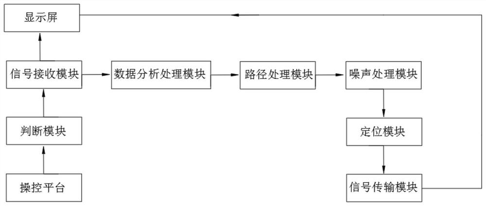
The invention discloses a low-voltage power line fault detection positioning system and a fault detection method, and belongs to the technical field of power line fault detection, and the system comprises a control platform, a judgment module, a data receiving module, a display screen, a data analysis processing module, a path analysis module, a noise processing module, a positioning module and an information transmission module. The control platform is in communication connection with the judgment module, the judgment module is in communication connection with the data receiving module, the display screen and the data analysis and processing module are both in communication connection with the data receiving module, and the data analysis and processing module is in communication connection with the path analysis module; and according to the invention, the specific reason of the low-voltage power line fault can be effectively detected, the fault section of the fault low-voltage power line can be accurately positioned, replacement and maintenance by workers are facilitated, and the detection and maintenance efficiency is improved.

Description

technical field [0001] The invention relates to the technical field of power line fault detection, in particular to a low-voltage power line fault detection and positioning system and a fault detection method. Background technique [0002] Low-voltage power lines, also known as low-voltage cables, are conductors covered with insulating layers, protective layers, shielding layers, etc. used to transmit power or signal currents and signal voltages. According to the voltage, it can be divided into high-voltage cables and low-voltage cables. Compared with low-voltage overhead lines and low-voltage overhead insulated lines, although low-voltage cable lines are more expensive and difficult to lay and maintain, they are reliable in operation, do not erect poles, do not occupy the ground, are not unsightly, and are less affected by the outside world. characteristics, and are widely used in low-voltage power distribution systems; however, low-voltage power lines are easily affected ...

Claims


Application Information

Patent Timeline
Patent Type & Authority Applications(China)
IPC IPC(8): G01R31/08G01R31/52G01R31/58G01R31/12G01R19/165
CPCG01R31/085G01R31/52G01R31/58G01R31/1272G01R31/1209G01R19/16576G01R19/16538Y04S10/52
Inventor 徐通通陈浩
Owner 山东卓文信息科技有限公司
Why Eureka
Try Eureka