
Control system and control method for U-shaped water seal of gas pipeline

A control system and gas pipeline technology, applied in the pipeline system, functional valve type, gas/liquid distribution and storage, etc., can solve problems such as low efficiency, gas leakage, and low reliability, so as to improve operating efficiency and ensure personal safety , the effect of improving safety

Active Publication Date: 2021-07-09
SGIS SONGSHAN CO LTD
View PDF6 Cites 2 Cited by
  • Summary
  • Abstract
  • Description
  • Claims
  • Application Information

AI Technical Summary

Problems solved by technology

[0003] In the prior art, the U-shaped water seal of the gas pipeline is manually operated to open and close the valve for water replenishment, and there is no device on site to detect the operating state of the U-shaped water seal
The manual control of the U-shaped water seal has the following disadvantages: 1. The unattended on-site mode is realized in the cabinet area, and the operating status of the U-shaped water seal depends on the regular on-site inspection by the operator to know whether it is short of water; 2. When opening and closing the U-shaped water seal, it is necessary to manually switch the valve on site to replenish water or drain water, and the operators are concentrated in the centralized control center far away from the operation site. The efficiency of manual operation is low, and it is difficult to control the valve switch in time , it is easy to make the U-shaped water seal unable to replenish water in time, resulting in gas leakage; 3. When operating the valve switch, the operator is required to have a strong sense of responsibility, and the reliability is low; 4. The cabinet area is a major hazard area. Personnel need to enter the cabinet area frequently. Once the gas equipment and facilities in operation cause gas leakage due to aging and other reasons, safety accidents of gas poisoning are very likely to occur, and there are great safety hazards

Method used


Image

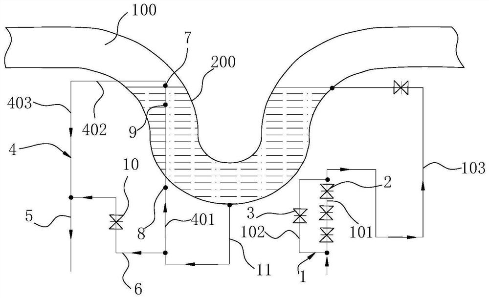
  • Control system and control method for U-shaped water seal of gas pipeline
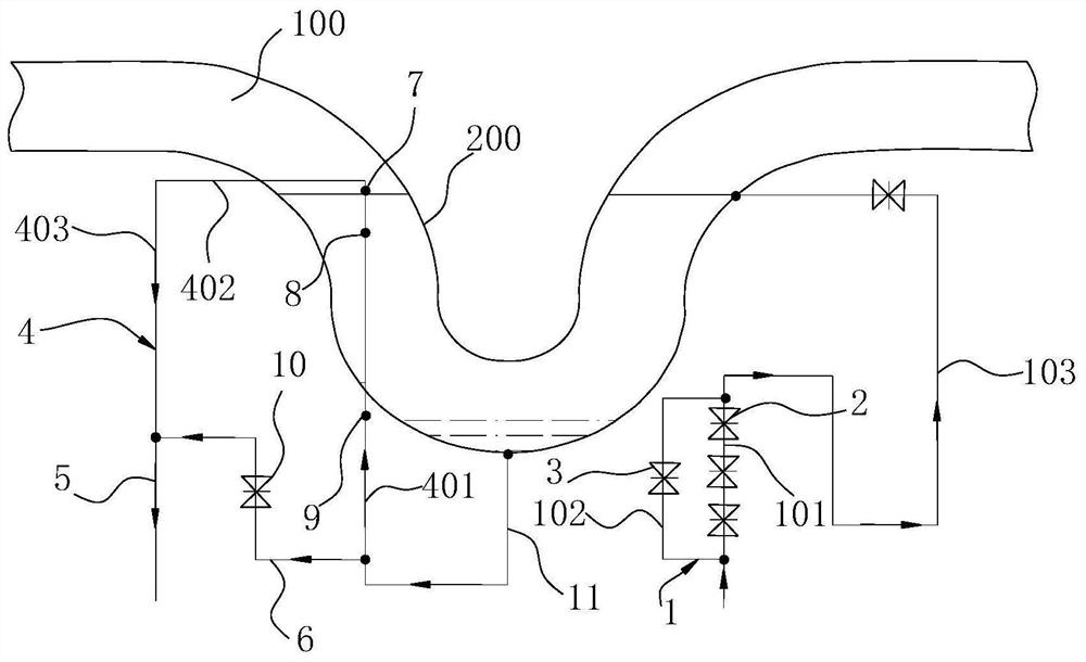
  • Control system and control method for U-shaped water seal of gas pipeline

Examples


Embodiment Construction

[0027] In order to make the technical problems solved by the present invention, the technical solutions adopted and the technical effects achieved clearer, the technical solutions of the embodiments of the present invention will be further described in detail below in conjunction with the accompanying drawings. Obviously, the described embodiments are only the technical solutions of the present invention. Some, but not all, embodiments. Based on the embodiments of the present invention, all other embodiments obtained by those skilled in the art without creative efforts fall within the protection scope of the present invention.

[0028] In the description of the present invention, unless otherwise clearly specified and limited, the terms "connected", "connected" and "fixed" should be understood in a broad sense, for example, it can be a fixed connection, a detachable connection, or an integrated ; It can be a mechanical connection or an electrical connection; it can be a direct...


PUM


Abstract

The invention discloses a control system and control method for a U-shaped water seal of a gas pipeline. The control system for the U-shaped water seal of the gas pipeline comprises a pipeline assembly, a probe assembly, an electromagnetic valve assembly and a PLC, wherein the pipeline assembly comprises a water inlet pipe, a drainage pipe, a high overflow pipe and a low overflow pipe; the probe assembly comprises a first probe and a second probe which are arranged on the high overflow pipe; the first probe is used for monitoring whether the water level in a U-shaped pipe section reaches the first height water level or not, the second probe is used for monitoring whether the water level in the U-shaped pipe section is lower than the second high water level or not, and the first height water level is located above the second height water level; the electromagnetic valve assembly comprises a first electromagnetic valve and a second electromagnetic valve which are arranged on the water inlet pipe; the first probe, the second probe, the first electromagnetic valve and the second electromagnetic valve are all in communication connection with the PLC; and the PLC can control opening and closing of the first electromagnetic valve and the second electromagnetic valve. The control system has the advantages of being high in control efficiency and good in safety performance.

Description

technical field [0001] The invention relates to the technical field of gas pipeline partitions, in particular to a gas pipeline U-shaped water seal control system and control method. Background technique [0002] Generally, the gas pipeline in the gas cabinet area is equipped with a U-shaped water seal to cut off the connection between the gas facility and the main network. The diameter of the U-shaped water seal varies from 1.2 meters to 3.2 meters. The U-shaped water seal of the gas pipeline is an important part to ensure the production safety of gas storage and gas transportation. [0003] In the prior art, the U-shaped water seal of the gas pipeline is replenished by manually operating the valve to open and close, and there is no device for detecting the running state of the U-shaped water seal on site. The manual control of the U-shaped water seal has the following disadvantages: 1. The unattended on-site mode is realized in the cabinet area, and the operating status o...

Claims


Application Information

Patent Timeline
Patent Type & Authority Applications(China)
IPC IPC(8): F16K21/18F16K37/00F17D5/00
CPCF17D5/005F16K37/005F16K21/185
Inventor 杨定生刘钦伟危中良唐景涛陈环刘振辉李雪安戴金华李燕辉劳海权赵小平李靖任珲
Owner SGIS SONGSHAN CO LTD
Learn More