An oil-water separation device and oily sludge drying system

A technology of oil-water separation device and separation zone, which is applied in water/sludge/sewage treatment, dehydration/drying/concentrated sludge treatment, separation methods, etc., and can solve the problems of low separation efficiency, large space occupation, and poor separation effect , to achieve the effect of improving separation efficiency, saving floor space and simple structure

Active Publication Date: 2022-07-05
BC P INC CHINA NAT PETROLEUM CORP +1
View PDF7 Cites 0 Cited by
  • Summary
  • Abstract
  • Description
  • Claims
  • Application Information

AI Technical Summary

Problems solved by technology

However, the oil-water separator of the gravity partition type takes up a large space and has low separation efficiency, while the oil-water separator with auxiliary structures such as inclined plates or coalescing packing has a complex structure, is not easy to overhaul, and is easy to block, and the actual separation effect poor

Method used


Image

  • An oil-water separation device and oily sludge drying system
  • An oil-water separation device and oily sludge drying system
  • An oil-water separation device and oily sludge drying system

Examples


Embodiment 1

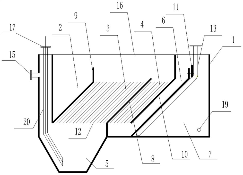
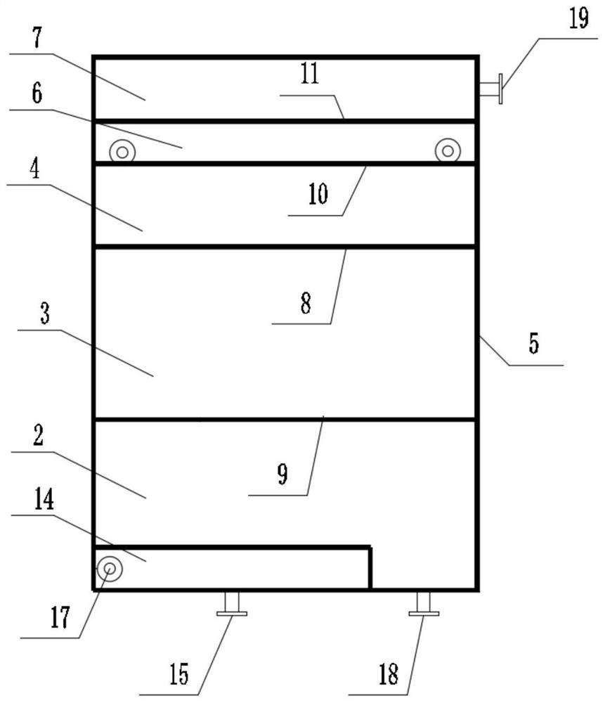
[0055] This embodiment provides an oil-water separation device, refer to figure 1 and figure 2 As shown, it includes: a tank body 1, an oil storage area 2, a first separation area 3, a second separation area 4, a mud storage bucket 5, a water level adjustment area 6 and a water storage area 7 arranged in the tank body 1; The mud storage hopper 5 is communicated with the first separation zone 3, and the second separation zone 4 is communicated with the water level adjustment zone 6; A partition 8; a first inner partition 9 is arranged between the first separation area 3 and the oil storage area 2; a second inner partition 9 is arranged between the second separation area 4 and the water level adjustment area 6 Partition 10, a water level adjusting weir 11 is arranged between the water level adjusting area 6 and the water storage area 7; the separating partition 8, the first inner partition 9 and the water level adjusting weir 11 The height of the top surface increases in turn...

Embodiment 2

[0087] Based on the same inventive concept, an embodiment of the present invention also provides an oily sludge drying system, including the oil-water separation device in the above embodiment.

[0088] In the embodiment of the present invention, for the specific structure of the oil-water separation device of the oily sludge drying system, reference may be made to the description of the above-mentioned Embodiment 1, which will not be repeated here.


PUM


Abstract

The present disclosure relates to an oil-water separation device and an oily sludge drying system. The oil-water separation device includes: a box body, an oil storage area arranged in the box body, a first separation area, a second separation area, a mud storage bucket, a water level adjustment area and a water storage area; the mud storage bucket is communicated with the first separation area , the second separation area is communicated with the water level adjustment area; a separation baffle is arranged between the first separation area and the second separation area; a first inner baffle is arranged between the first separation area and the oil storage area; the second separation area A second inner baffle is arranged between the water level adjustment area, and a water level adjustment weir is arranged between the water level adjustment area and the water storage area; the top surface heights of the separation baffle, the first inner baffle and the water level adjustment weir increase in sequence. Large; the height of the second inner partition is greater than the height of the water level adjusting weir plate and less than or equal to the height of the upper plane of the box. The oil-water separation device has the advantages of simple structure, good oil-water separation effect, high separation efficiency, convenient maintenance and strong practicability.

Description

technical field [0001] The present disclosure relates to an oil-water separation device and an oily sludge drying system. Background technique [0002] During the drying process of oily sludge, the light oil in the oily sludge is heated and gasified to obtain gas-phase exhaust gas. Therefore, it is necessary to cool the gas-phase exhaust gas to reduce volatile organic compounds (Volatile Organic Compounds, VOC). However, during the exhaust gas treatment process, the condensed high-temperature wastewater has a high oil content, and the oil in the wastewater may cause continuous volatilization under high temperature conditions. Therefore, according to the "Petrochemical Industry Pollutant Discharge Standard" GB 31571-2015, the oil content in the indirect discharge water is required to be less than 20mg / L, and the oily wastewater needs to be pretreated before it can enter the drainage system. [0003] In the prior art, an oil-water separator is usually used for treatment of su...

Claims


Application Information

Patent Timeline
Patent Type & Authority Patents(China)
IPC IPC(8): C02F9/02C02F11/12C02F1/40C02F101/32C02F103/36
CPCC02F1/40C02F11/12C02F2301/08C02F2209/42C02F2001/007C02F2209/09C02F2303/06C02F2101/32C02F2103/365Y02A50/20
Inventor 季先进徐坡俱虎良牛国瑞魏晓明张伟上官少鹏陈星何静怡高超张超马捷
Owner BC P INC CHINA NAT PETROLEUM CORP
Why Eureka
Try Eureka