
A mechanical deicing device and deicing method for electrothermally divided regions

A technology that divides areas and machinery, and is applied in deicing devices, aircraft parts, transportation and packaging, etc., and can solve problems such as low energy consumption, large residual ice, and failure to achieve flight protection, achieving low energy consumption, deodorization, etc. good ice effect

Active Publication Date: 2021-10-12
LOW SPEED AERODYNAMIC INST OF CHINESE AERODYNAMIC RES & DEV CENT
View PDF9 Cites 0 Cited by
  • Summary
  • Abstract
  • Description
  • Claims
  • Application Information

AI Technical Summary

Problems solved by technology

[0002] When the aircraft is flying under icing weather conditions, when the outer parts of the fuselage collide with supercooled water droplets, the surface will freeze rapidly, and the ice will accumulate to form an ice layer similar to the outline of the parts. The excellent aerodynamic shape is destroyed, resulting in a decline in the flight performance of the aircraft, and in severe cases, it will cause a flight safety accident
In order to avoid the hazards caused by icing, effective protective measures must be taken in areas prone to icing on the aircraft. The main anti-icing methods include hot air anti-icing, electric heating anti-icing, mechanical deicing, etc. However, the energy reserves of the aircraft itself are limited. Energy consumption for icing protection accounts for a small proportion, and icing is a very complicated process. Sometimes there are some special circumstances, and only a single method to solve the icing problem may not meet the requirements of flight protection
[0003] For example, airfoil components mainly occur in the area of ​​the leading edge when icing occurs. The entire surface of the leading edge of the component can be intermittently heated by means of electric heating to reduce the adhesion between icing and its surface, and use the aerodynamic external force during flight to remove the surface. For icing, if the ice shape at the leading edge is relatively symmetrical, the external force on the ice is relatively uniform, and the ice will continue to adhere to the surface of the leading edge, or the temperature of the entire surface can be controlled above zero for direct anti-icing, but in this case, a long time Power consumption is relatively large; vibrating elements can also be arranged on the inner surface of the front edge to destroy the ice structure through mechanical vibration, and the cracked ice will fall off under aerodynamic force to achieve the purpose of deicing. Ice leads to more residual ice

Method used


Image

  • A mechanical deicing device and deicing method for electrothermally divided regions
  • A mechanical deicing device and deicing method for electrothermally divided regions
  • A mechanical deicing device and deicing method for electrothermally divided regions

Examples


Embodiment 1

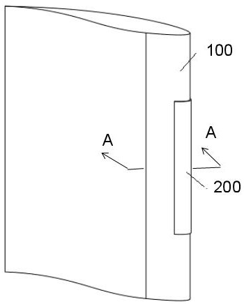
[0032] Embodiment 1 of the present invention provides a mechanical deicing device 300 for electrothermally divided regions, including:

[0033] A plurality of electric heating elements 301, the plurality of electric heating elements 301 are arranged in an array;

[0034] A plurality of vibrating elements 302, each of the vibrating elements 302 is set in a one-to-one correspondence with the position of each of the electric heating elements 301;

[0035] The plurality of electric heating elements 301 and the plurality of vibration elements 302 are distributed on the first surface 1011 and the second surface 1012 of the airfoil model 100, wherein the first surface 1011 and the second surface 1012 constitute The leading edge region of the airfoil model 100, and the first surface 1011 and the second surface 1012 are separated by a leading edge line 1014; the upper surface of the first surface 1011 and the second surface 1012 has a skin 1013 , the multiple electric heating elements...

Embodiment 2

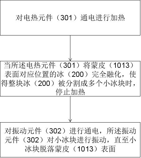
[0054] The present invention also provides a method for deicing by using the above-mentioned mechanical deicing device for electrothermal division area, such as Figure 5 shown, including the following steps:

[0055] Step S1: energize the heating element 301 for heating;

[0056] Step S2: Stop heating when the electric heating element 301 completely melts the ice 200 at the corresponding position on the surface of the skin 1013 so that the whole block of ice 200 is divided into multiple small ice cubes;

[0057] Step S3: power on the vibrating element 302, and the vibrating element 302 vibrates the small ice until the small ice falls off the surface of the skin 1013.

[0058] In the above solution, when the aircraft needs to be deiced, multiple electric heating elements 301 are heated at the same time, and when the ice layer on the surface of the skin 1013 corresponding to the electric heating element 301 melts and evaporates, the whole piece of ice 200 is divided into multi...


PUM


Abstract

The present invention is applicable to the field of deicing technology, and provides a mechanical deicing device and a deicing method for electrothermal division areas, wherein the deicing device includes: a plurality of electric heating elements arranged in an array; a plurality of vibration elements , each vibrating element is set in one-to-one correspondence with the position of each electric heating element; a plurality of electric heating elements and a plurality of vibrating elements are distributed on the first surface and the second surface of the airfoil model, wherein the first surface and the second surface It constitutes the leading edge area of ​​the airfoil model, and the first surface and the second surface are separated by the leading edge line; the upper surface of the first surface and the second surface has a skin, and a plurality of electric heating elements are embedded in the skin, and a plurality of vibration The components are mounted on the inner surface of the skin. The whole block of ice is divided into small ice cubes by the present invention, and then vibration deicing is performed on each small ice cube, the deicing efficiency is high, and there is no residual ice, and the deicing effect is good.

Description

technical field [0001] The invention relates to the field of deicing, in particular to an electrothermally divided area mechanical deicing device and a deicing method. Background technique [0002] When the aircraft is flying under icing weather conditions, when the outer parts of the fuselage collide with supercooled water droplets, the surface will freeze rapidly, and the ice will accumulate to form an ice layer similar to the outline of the parts. The excellent aerodynamic shape is destroyed, resulting in a decline in the flight performance of the aircraft, and in severe cases, it will cause a flight safety accident. In order to avoid the hazards caused by icing, effective protective measures must be taken in areas prone to icing on the aircraft. The main anti-icing methods include hot air anti-icing, electric heating anti-icing, mechanical deicing, etc. However, the energy reserves of the aircraft itself are limited. The energy consumption for icing protection accounts ...

Claims


Application Information

Patent Timeline
Patent Type & Authority Patents(China)
IPC IPC(8): B64D15/12B64D15/16
CPCB64D15/12B64D15/16
Inventor 柳庆林李自雨冉林林伟
Owner LOW SPEED AERODYNAMIC INST OF CHINESE AERODYNAMIC RES & DEV CENT
Learn More