
Projection ray machine

A technology of projection light machine and projection lens, which is applied in the direction of optics, instruments, projection devices, etc., and can solve the problems of poor heat dissipation, reduced projection quality of projection light machine, and difficulty in effective separation

Active Publication Date: 2021-07-06
SHENZHEN ANHUA OPTOELECTRONICS TECH
View PDF6 Cites 0 Cited by
  • Summary
  • Abstract
  • Description
  • Claims
  • Application Information

AI Technical Summary

Problems solved by technology

When the Off light heat dissipation structure with structural characteristics is applied to the second type of DMD light modulator, on the one hand, because the size of the Off light beam in the long side direction of the projection screen is larger, it is difficult for the suspended light shielding part to fully cover the Off light beam. The light beam and provide sufficient heat conduction flux, so the heat dissipation effect is poor; on the other hand, the size of the suspended and sheet-shaped light shielding part is more difficult to control, or it is easier to deform under thermal stress, thereby interfering with the adjacent components. Assembly, and it is difficult to effectively separate other stray light from the On beam when the DMD light modulator is in the bright state, thereby reducing the overall projection quality of the projection light machine

Method used


Image

  • Projection ray machine
  • Projection ray machine
  • Projection ray machine

Examples


Embodiment Construction

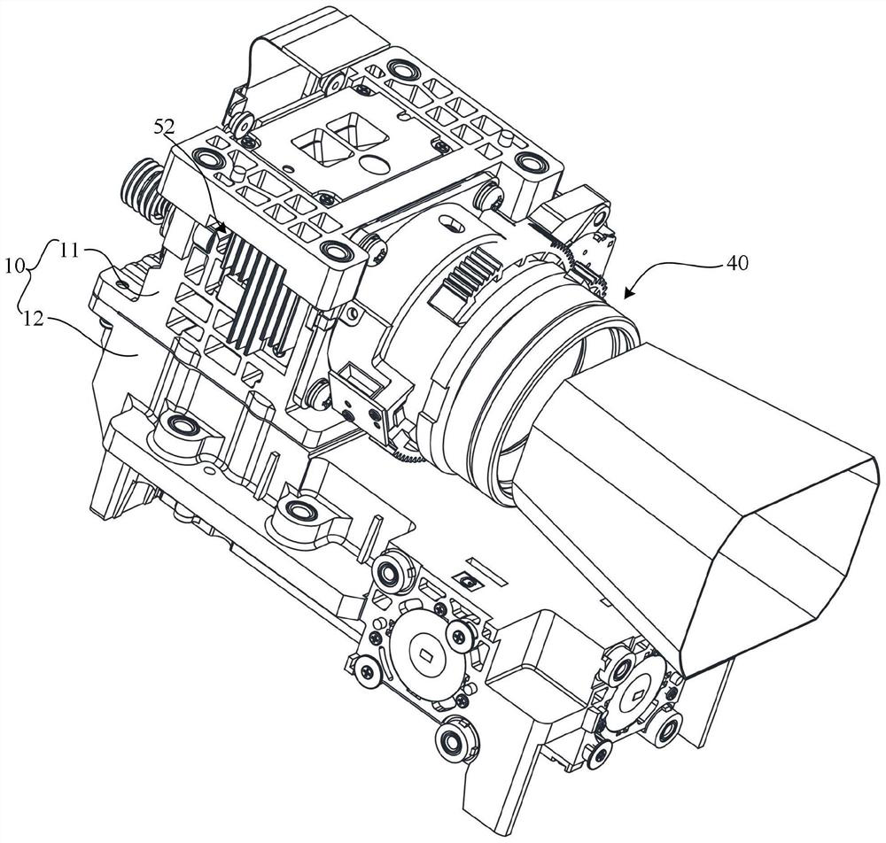
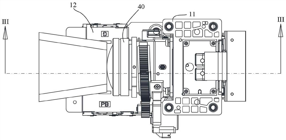
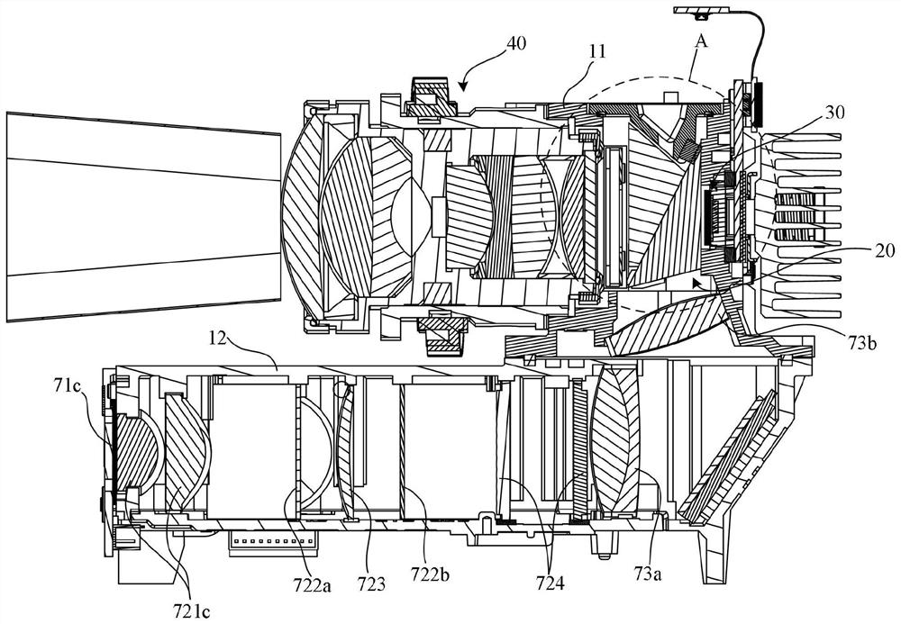
[0049] Please refer to Figure 1 to Figure 4 , Figure 7 ,and Figure 14 , In one embodiment, the optical projection machine of the present invention includes a housing 10, a dichroic prism 20, a DMD light modulator 30, a projection lens 40, and a light-shielding heat dissipation assembly 50. The housing 10 has an inner cavity 111 and communicates with the inner cavity 111. The front mounting port 112 and the rear mounting port 113; the inner wall surface of one side of the inner cavity 111 in the left and right direction is provided with a plug port 114 adjacent to the front mounting port 112; the housing 10 is far away from the plug port 114 in the left and right direction The outer surface of the corresponding socket 114 is provided with a through groove 115;

[0050] The DMD light modulator 30 is installed in the rear installation port 113, and the light modulation area of ​​the DMD light modulator 30 is set forward; the projection lens 40 is installed in the front insta...


PUM


Abstract

The present invention discloses a projection light machine which comprises a shell, a beam splitter prism, a DMD light modulator, a projection lens and a shading heat dissipation assembly, the shell is provided with an inner cavity, a front installation opening and a rear mounting port, and a plugging opening and a penetrating groove which are opposite to each other are formed in the position, close to the front mounting port, of the inner wall face of one side in the left-right direction; the DMD light modulator and the projection lens are respectively mounted at the rear mounting port and the front mounting port; the beam splitter prism is located in the inner cavity and comprises an initial incident plane, an emergent incident plane and an imaging emergent plane; the shading and heat dissipation assembly comprises a shading piece and a heat dissipation piece; the shading piece penetrates through the penetrating groove and extends into the inner cavity, the inner end is inserted into the insertion port, and the outer end is connected with the heat dissipation piece; the shading piece comprises a first shading part, and the first shading part is arranged opposite to the imaging emergent surface; and in the left-right direction, the length of the first shading piece is greater than that of the imaging emergent surface. The projection light machine is good in heat dissipation and projection effect when the DMD light modulator with long-side incident illumination light beams is applied to the projection light machine.

Description

technical field [0001] The invention relates to the technical field of optical projection equipment, in particular to a projection light machine. Background technique [0002] The core component of a micro-projector is a projection light machine. In order to realize the projection of a rectangular widescreen image, the existing projection light machine usually uses such a DMD light modulator, that is, it receives the incident light from the short side of the rectangular modulation area of ​​the DMD light modulator. lighting beam. At present, there is also a DMD light modulator whose rectangular modulation area takes the long side as the incident side of the illumination beam. When the two kinds of DMD light modulators with the same rectangular modulation area are in the dark state (Off state), the length of the Off light beam of the DMD light modulator whose incident light beam is incident on the short side in the long side direction of the projection screen is L1, and the ...

Claims


Application Information

Patent Timeline
Patent Type & Authority Applications(China)
IPC IPC(8): G03B21/00G03B21/14G03B21/16
CPCG03B21/008G03B21/142G03B21/16
Inventor 朱青高怡玮杨浩孙峰
Owner SHENZHEN ANHUA OPTOELECTRONICS TECH
Learn More