
Range hood and control method thereof

The technology of a range hood and a control method is applied in the directions of removing range hood, heating method, household heating, etc., and can solve the problem of easy escape of range hood and the like

Pending Publication Date: 2021-07-06
GREE ELECTRIC APPLIANCES INC
View PDF0 Cites 0 Cited by
  • Summary
  • Abstract
  • Description
  • Claims
  • Application Information

AI Technical Summary

Problems solved by technology

[0003] Therefore, the technical problem to be solved by the present invention is to overcome the defect that the oil fume of the top-suction range hood is easy to escape in the prior art, so as to provide a range hood that can reduce the emission of oil fume and improve the effect of oil absorption.

Method used


Image

  • Range hood and control method thereof
  • Range hood and control method thereof
  • Range hood and control method thereof

Examples


Embodiment 1

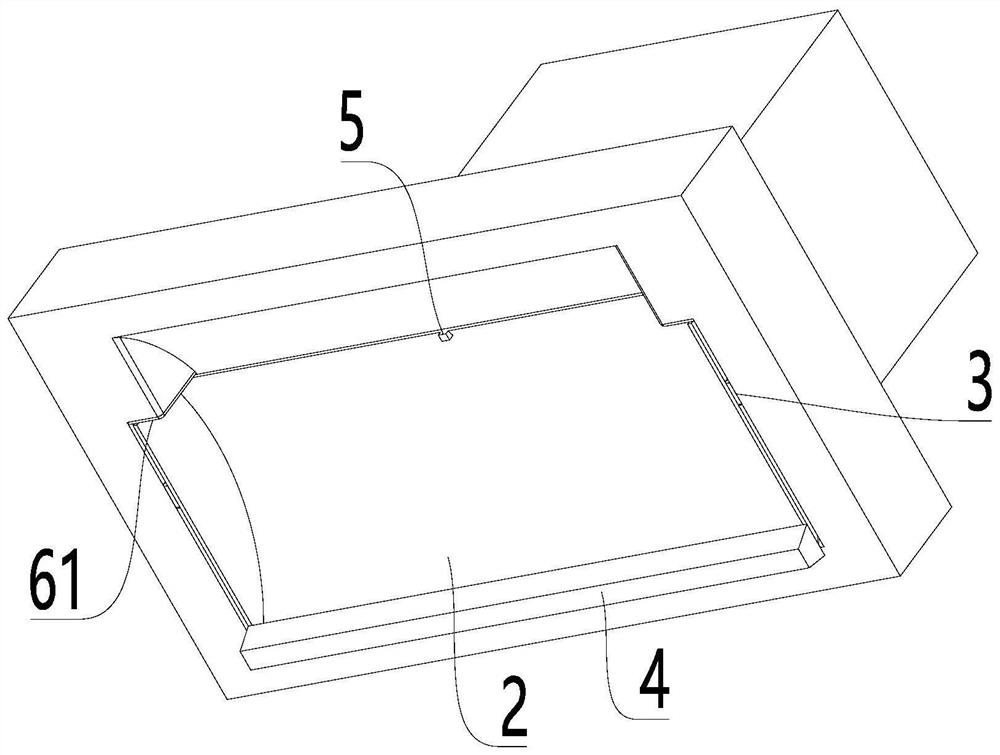
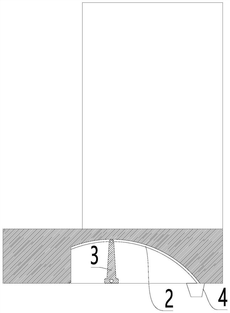
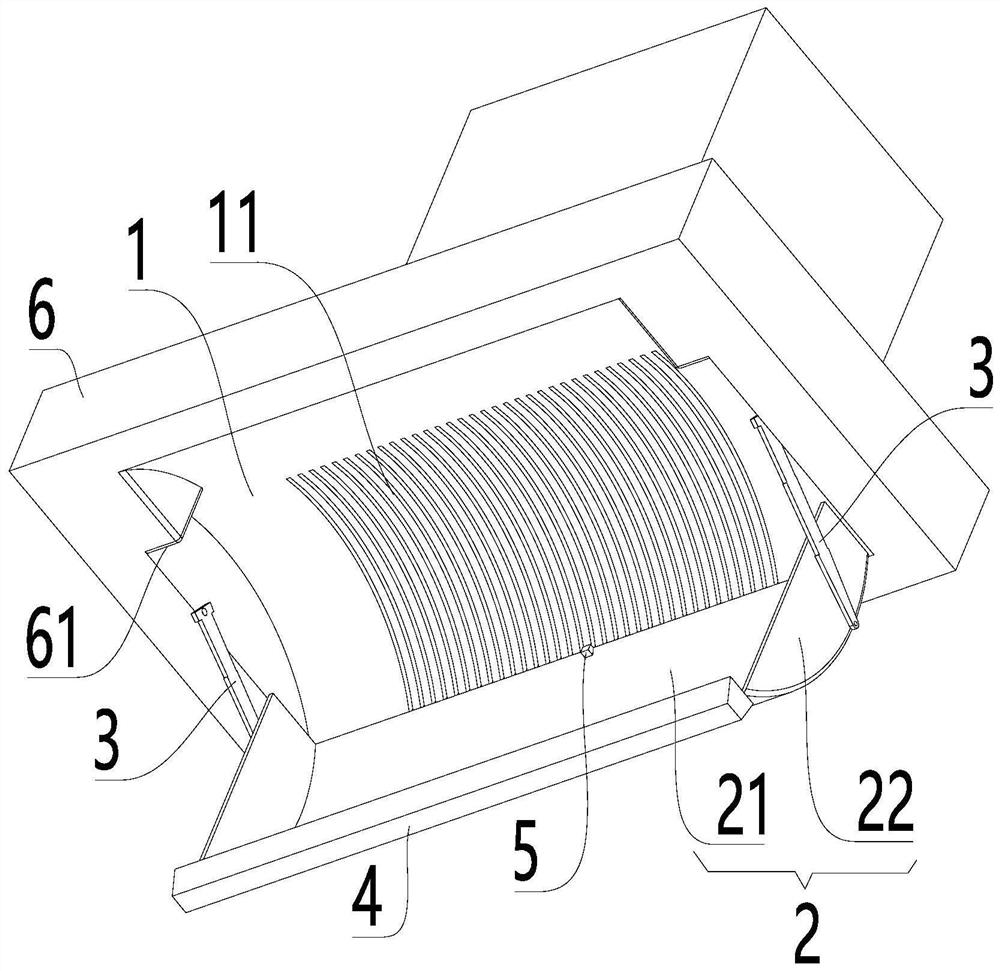
[0050] combine Figure 1-Figure 5 As shown, the range hood provided in this embodiment includes:

[0051] Range hood body 6;

[0052]The oil screen 11 is arranged on the body 6 of the range hood;

[0053] The smoke guide plate 2 is movably connected with the range hood body 6, the smoke guide plate 2 has an initial state of at least partially covering the oil screen 11, and a working state of making way for the oil screen 11; as well as

[0054] The guide part 3 is adapted to guide the smoke guide plate 2 to switch between the working state and the initial state relative to the range hood body 6; when the smoke guide plate 2 is switched from the initial state to the working state , the first end of which extends downward along the height direction.

[0055] The range hood provided in this embodiment is provided with a smoke guide plate 2 that is movably connected to the range hood body 6, and when the smoke guide plate 2 is switched from the initial state to the working st...

Embodiment 2

[0090] This embodiment provides a control method for the range hood described in Embodiment 1, including:

[0091] When the range hood is in the standby state, turn on the smoke sensor module;

[0092] Based on the oil smoke concentration obtained by the smoke sensor module, the position state of the smoke deflector is controlled.

[0093] Specifically, the controlling the position state of the smoke guide plate based on the oil smoke concentration obtained by the smoke sensing module includes:

[0094] When the oil fume concentration is greater than C1, adjust the smoke deflector to the working state;

[0095] When the oil fume concentration is less than C2, adjust the smoke deflector to an initial state; wherein, C1>C2.

[0096]When the range hood is in the standby state, the smoke sensor module is turned on. If the smoke sensor module detects oil smoke and reaches a certain concentration C1, it will automatically control the synchronous opening of the smoke guide plate an...


PUM


Abstract

The invention relates to the technical field of kitchen appliances, in particular to a range hood and a control method thereof. The range hood comprises a range hood body, an oil screen, a lampblack guide plate and a guide portion, wherein the oil screen is arranged on the range hood body; the lampblack guide plate is movably connected with the range hood body, and the lampblack guide plate has an initial state of at least partially covering the oil screen and a working state of keeping away from the oil screen; the guide portion is suitable for guiding the lampblack guide plate to be switched between the working state and the initial state relative to the range hood body; and when the lampblack guide plate is switched from the initial state to the working state, the first end of the lampblack guide plate extends downwards in the height direction. According to the range hood, the contact time of lampblack and the lampblack guide plate is prolonged, the condensation area of the lampblack is increased indirectly, the filtering effect of the lampblack is improved, and the effect of combining a top range hood and a side range hood is achieved.

Description

technical field [0001] The invention relates to the technical field of kitchen appliances, in particular to a range hood and a control method thereof. Background technique [0002] Range hoods have become one of the indispensable kitchen equipment in modern families. Common range hoods include top-suction and side-suction types. widely. However, compared with the side-suction range hood, the top-suction range hood has a longer distance for the oil fume to enter the fan because the air inlet is far away from the stove, and it takes a longer time to reach the fan. Oily fumes are easy to escape, especially some oily fumes will escape from both sides, resulting in the defects that the top-suction range hood often has the disadvantages that the oily fume is easy to escape and the effect of collecting smoke is poor; in addition, the top-suction range hood oil Nets are often exposed to the air for a long time, with low aesthetics and easy to accumulate dust. After dust and grease...

Claims


Application Information

Patent Timeline
IPC IPC(8): F24C15/20
CPCF24C15/2021F24C15/2085
Inventor 宁菲许宁胡小帝温汉杰梁荣于建中
Owner GREE ELECTRIC APPLIANCES INC
Learn More