
Glass panel feeding and discharging method

A glass panel and cutting technology, which is applied in the direction of conveyor objects, furnaces, rollers, etc., can solve the problems of inaccurate collection box position, inaccurate feeding of glass panels, and low degree of equipment automation

Inactive Publication Date: 2021-07-06
郑少华
View PDF9 Cites 0 Cited by
  • Summary
  • Abstract
  • Description
  • Claims
  • Application Information

AI Technical Summary

Problems solved by technology

[0004] The existing technology has the following deficiencies: 1. When loading and unloading glass panels, each process is manually completed on a single workbench, and then the product flow is sent to the next workbench through the conveyor line for the next process process, and finally completed The loading and unloading process of the glass panel; and each process requires manual participation and auxiliary feeding flow, which affects the processing efficiency of the entire device and results in a low degree of automation of the entire equipment
2. Manually move the glass panel from the loading station to the feeding end of multiple collection devices, which increases the labor intensity of workers and reduces the efficiency of glass panel removal
3. The lifting drive assembly directly drives the lifting bottom plate with a flat upper surface to move, and then drives the collection box on the lifting bottom plate to move up to different heights to receive multiple glass panels; while the lifting bottom plate with a flat upper surface has no impact on the collection box. Limiting effect, the collection box is prone to move when it moves up and down, resulting in inaccurate position of the collection box, and thus making it impossible for the glass panel to be accurately fed into the collection box

Method used


Image

  • Glass panel feeding and discharging method
  • Glass panel feeding and discharging method
  • Glass panel feeding and discharging method

Examples


Embodiment 1

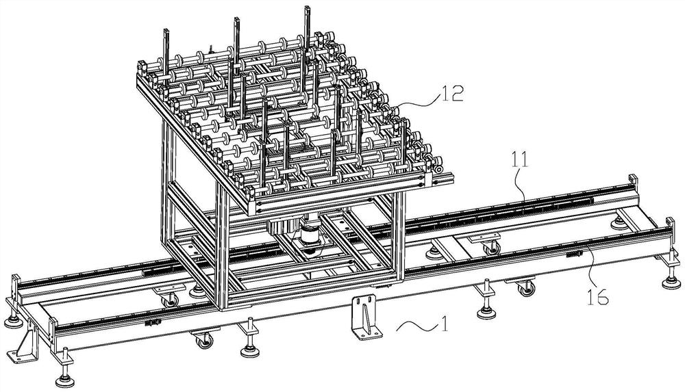
[0028] like Figure 9 Shown is a glass panel loading and unloading equipment, which includes a frame and a conveying device 1 fixed on the frame, a collecting device 2, and a feeding and moving device; the feeding end and the discharging end of the conveying device 1 are respectively connected to the glass panel The feeding station is connected to the feed end of multiple collection devices 2; the feed end and discharge end of the unloading and moving device are respectively connected to the discharge end of the collection device 2 and the unloading station; the conveying device 1 is used to transport the glass panel Transport to different collection devices 2; the collection device 2 is used to receive multiple glass panels; the unloading transfer device is used to unload the multiple glass panels collected in the collection device 2.

[0029] The product flow direction of the glass panel is: conveying device 1 to collecting device 2 to unloading and moving device.

[0030] ...


PUM


Abstract

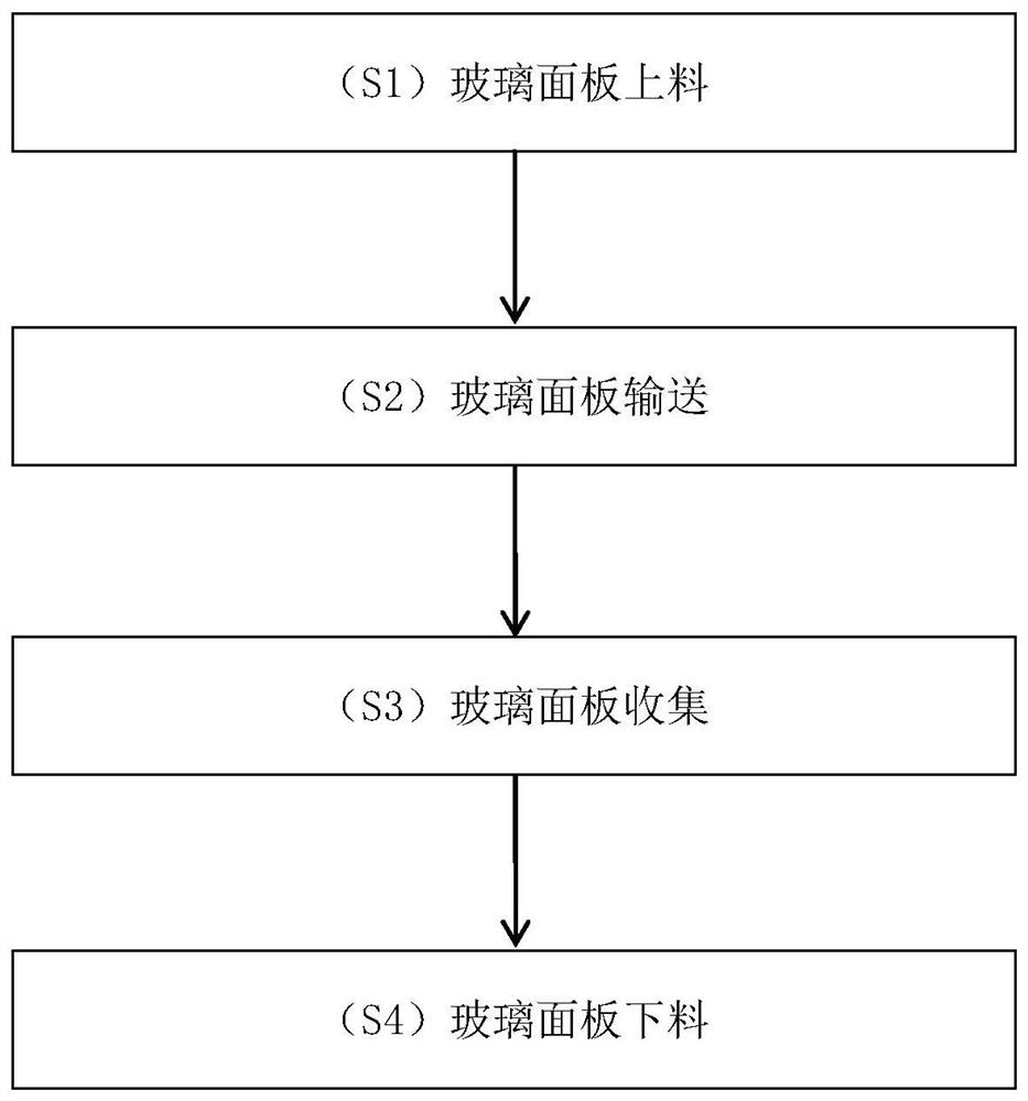
The invention relates to the field of glass panels, in particular to a glass panel feeding and discharging method. Equipment adopted by the method comprises a rack, a conveying device, a collecting device and a discharging and moving device, wherein the conveying device, the collecting device and the discharging and moving device are fixed to the rack; the conveying device comprises a conveying driving mechanism and a pushing mechanism; the collecting device comprises a collecting rack, a lifting mechanism and a collecting box body; and the method comprises the steps of glass panel feeding, glass panel conveying, glass panel collecting and glass panel discharging. According to the method, automatic feeding and discharging of the glass panels are achieved by arranging the conveying device, the collecting device and the discharging and moving device, and the automation degree of the whole equipment is improved.

Description

technical field [0001] The invention relates to the field of glass panels, in particular to a method for loading and unloading glass panels. Background technique [0002] Glass is an amorphous inorganic non-metallic material, generally made of various inorganic minerals (such as quartz sand, borax, boric acid, barite, barium carbonate, limestone, feldspar, soda ash, etc.) of. Its main components are silicon dioxide and other oxides. At present, existing electronic devices such as terminals have a layer of glass panels on the surface of their touch screens, and panels made of glass are widely used in various products such as liquid crystal displays, tablet computers, and smart phones. [0003] Chinese invention patent application (publication number CN208932514U, publication date: 20190604) discloses a device for automatic loading and unloading of glass panel materials, including a lifting assembly and a rotating assembly. Between the material levels and used to exchange t...

Claims


Application Information

Patent Timeline
IPC IPC(8): B65G49/06B65G47/82B65G13/06
CPCB65G49/064B65G49/068B65G47/82B65G13/06
Inventor 郑少华刘良军刘向东
Owner 郑少华
Learn More