Material surface grinding equipment for high-end equipment manufacturing

A technology for equipment manufacturing and material, applied in the field of material surface grinding equipment, it can solve the problems of manpower consumption, random movement of materials, and inability to accurately position the material, and achieve the effect of improving grinding efficiency, saving labor, and easily limiting the original placement position.

Active Publication Date: 2021-07-02
山东至信晟宇机械制造有限公司
View PDF7 Cites 3 Cited by
  • Summary
  • Abstract
  • Description
  • Claims
  • Application Information

AI Technical Summary

Problems solved by technology

[0005] In order to overcome the disadvantages in the prior art of manually pushing materials, consuming manpower, moving materials randomly, being unable to accurately locate, and affecting grinding, the technical problem of the present invention is to provide a device that can automatically push materials, automatically and quickly complete grinding, and accurately limit the grinding position. , provide guidance for material movement, and limit the initial placement of materials. Material surface grinding equipment for high-end equipment manufacturing

Method used


Image

  • Material surface grinding equipment for high-end equipment manufacturing
  • Material surface grinding equipment for high-end equipment manufacturing
  • Material surface grinding equipment for high-end equipment manufacturing

Examples


Embodiment 1

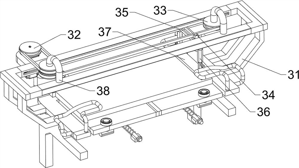
[0030] A material surface grinding equipment for high-end equipment manufacturing, such as figure 1 , figure 2 and image 3 As shown, it includes a workbench 1, a motor 2, a grinding mechanism 3 and a positioning mechanism 4, the upper left side of the workbench 1 is provided with a grinding mechanism 3, the front side of the left part of the grinding mechanism 3 is provided with a motor 2, and the left side of the workbench 1 is provided with a There is a positioning mechanism4.

[0031] The grinding mechanism 3 includes a first mounting frame 31, a first transmission assembly 32, a second transmission assembly 33, a connecting rod 34, a first sliding frame 35, a telescopic rod 36, a grinding block 37 and a support column 38, and the upper left side of the workbench 1 The first mounting frame 31 is connected to the side, and the motor 2 is installed on the left front side of the first mounting frame 31. The front and rear symmetrical support columns 38 are connected to the...

Embodiment 2

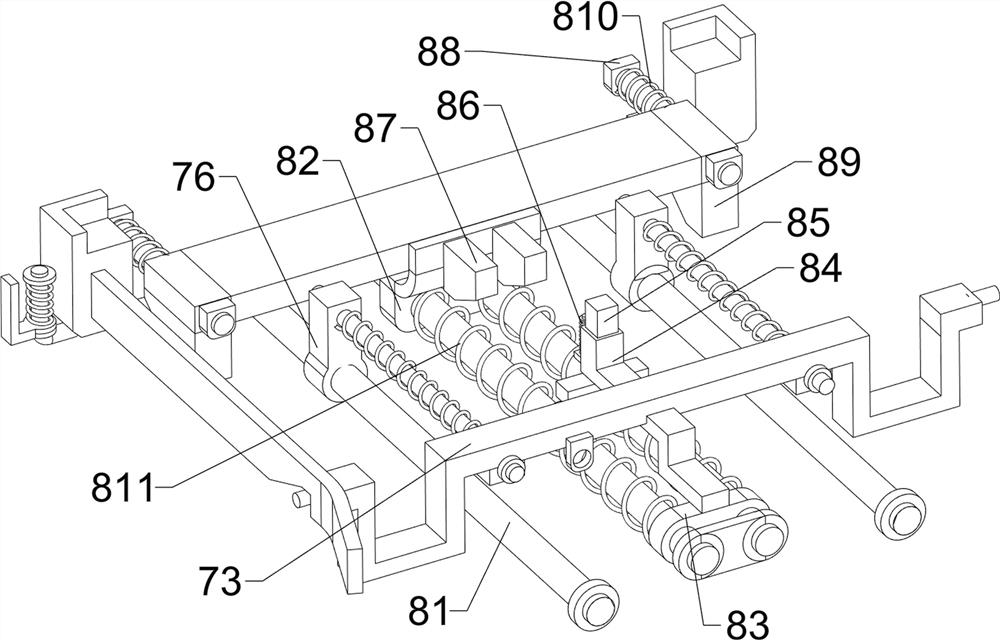
[0035] On the basis of Example 1, such as figure 1 , Figure 4 , Figure 5 , Figure 6 and Figure 7 As shown, a lifting mechanism 5 is also included, and the lifting mechanism 5 includes a guide frame 51, a first guide rod 52, a second spring 53 and a stop rod 54, and the left and right sides of the upper side of the workbench 1 are symmetrically connected with guides. Frame 51, the first guide rod 52 is connected with the inner lower side of the telescopic rod 36, and the first guide rod 52 is connected with a stop rod 54 in a sliding manner. A second spring 53 is connected between them, and the second spring 53 is sleeved on the first guide rod 52 .

[0036] In the starting state, the telescopic rod 36 moves forward from the rear side, driving the stop rod 54 to move forward, and after the lower side of the stop rod 54 touches the rear guide frame 51, it is pushed to move upward, thereby compressing the telescopic rod 36 and driving the grinding block 37 moves upwards,...


PUM


Abstract

The invention relates to grinding equipment, in particular to material surface grinding equipment for high-end equipment manufacturing. To solve the technical problem, the invention provides the material surface grinding equipment for high-end equipment manufacturing; and according to the material surface grinding equipment for high-end equipment manufacturing, materials can be automatically pushed, grinding can be automatically and rapidly completed, the grinding position is accurately limited, guiding is provided for material movement, and the initial placing position of the materials is limited. The material surface polishing equipment for high-end equipment manufacturing comprises a workbench, a motor and a positioning mechanism, wherein a polishing mechanism is arranged on one side of the upper part of the workbench; the motor is arranged on one side of the first part of the polishing mechanism; and the positioning mechanism is arranged on one side of the workbench. According to the material surface polishing equipment for high-end equipment manufacturing, by starting an air cylinder to push a limiting frame to move leftwards, a side baffle is pushed to move upwards, so that materials move leftwards along the side baffle; and therefore, the effect of automatically providing guiding for material conveying is achieved, and the situation that the materials deviate in the moving process to affect polishing is avoided.

Description

technical field [0001] The invention relates to a grinding device, in particular to a material surface grinding device used for high-end equipment manufacturing. Background technique [0002] The processing and manufacturing of high-end equipment requires the use of various materials. However, due to various reasons, the surface of the material is often uneven and has burrs. In order to finally make qualified and practical high-end equipment, the process of polishing the surface of the material is essential. few. [0003] The traditional material surface grinding technology mainly relies on the user to manually push the material under the grinding block, and use the existing equipment to drive the grinding block to move left and right to polish the material. This method, manually pushing the material, is very laborious and the grinding efficiency is low. Secondly, whether it is The initial placement position of the material, the route of the material transmission, and the p...

Claims


Application Information

Patent Timeline
Patent Type & Authority Applications(China)
IPC IPC(8): B24B27/00B24B9/00
CPCB24B27/00B24B27/0092B24B27/0069B24B9/00Y02P70/10
Inventor 罗加平
Owner 山东至信晟宇机械制造有限公司
Why Eureka
Try Eureka