Feeder control circuit for medical care
A technology for controlling circuits and feeders, applied in the medical field, can solve problems such as patient discomfort and inability to heat food
- Summary
- Abstract
- Description
- Claims
- Application Information
AI Technical Summary
Problems solved by technology
Method used
Image

Examples
Embodiment 1
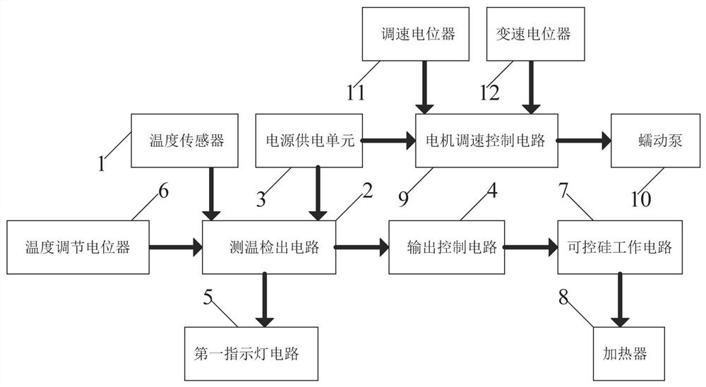
[0025] A feeder control circuit for medical care, such as figure 1 As shown, it includes a temperature sensor 1, a temperature detection circuit 2, a power supply unit 3, an output control circuit 4, a first indicator light circuit 5, a thyristor working circuit 7, a heater 8, and a motor speed control circuit 9 With the peristaltic pump 10, the temperature sensor 1 is connected to the input end of the temperature measurement detection circuit 2, the output end of the temperature measurement detection circuit 2 is connected to the input end of the output control circuit 4, and the output control circuit 4 The output terminal is connected to the input terminal of the thyristor working circuit 7, the output terminal of the thyristor working circuit 7 is connected to the heater 8, the input terminal of the first indicator light circuit 5 is connected to the temperature measurement detection circuit 2 The output end is connected, the output end of the motor speed control circuit 9...
Embodiment 2
[0028] On the basis of Example 1, such as figure 1 As shown, a temperature adjustment potentiometer 6 is also included, the temperature adjustment potentiometer 6 is connected to the input end of the temperature measurement and detection circuit 2 , and the power supply unit 3 supplies power to the temperature adjustment potentiometer 6 .
[0029] The nurse can set the heating temperature of the heater 8 through the temperature adjustment potentiometer 6, and then set the heating temperature of the food, so as to avoid the overheating of the food and cause the patient to feel uncomfortable.
[0030] Also include a speed regulating potentiometer 11 and a variable speed potentiometer 12, the speed regulating potentiometer 11 and the variable speed potentiometer 12 are all connected to the input end of the motor speed regulating control circuit 9, and the power supply unit 3 is a speed regulating potentiometer 11 and variable speed potentiometer 12 power supply.
[0031] When th...
Embodiment 3
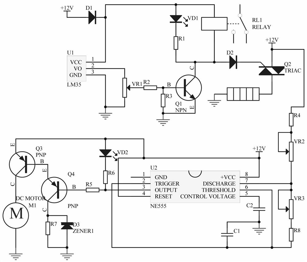
[0033] A feeder control circuit for medical care, such as figure 2 As shown, the temperature detection circuit 2 includes a temperature sensor 1LM35-U1 and a diode D1, the 3-pin of the temperature sensor 1LM35-U1 is grounded, and the 1-pin of the temperature sensor 1LM35-U1 is connected to the cathode of the diode D1 , the anode of the diode D1 is connected to +12V.
[0034]The thyristor working circuit 7 includes a triode Q1, a triac Q2, a resistor R1, a resistor R2, a resistor R3, a diode D2, a light emitting diode VD1 and a relay RL1, the emitter of the triode Q1 is grounded, and the triode The base of Q1 is connected to one end of the resistor R2, the base series resistor R3 of the triode Q1 is grounded, the collector of the triode Q1 is connected in series with the resistor R1 and the light-emitting diode VD1, and the anode of the light-emitting diode VD1 is connected to the temperature sensor 1LM35- The 1 pin of U1 is connected, the collector of the triode Q1 is connec...
PUM
 Abstract
Description
Claims
Application Information
 - R&D
- Intellectual Property
- Life Sciences
- Materials
- Tech Scout
- Unparalleled Data Quality
- Higher Quality Content
- 60% Fewer Hallucinations
Browse by: Latest US Patents, China's latest patents, Technical Efficacy Thesaurus, Application Domain, Technology Topic, Popular Technical Reports.
© 2025 PatSnap. All rights reserved.Legal|Privacy policy|Modern Slavery Act Transparency Statement|Sitemap|About US| Contact US: help@patsnap.com