Insulin drop timed shake-up rack
A technology of insulin and drip, applied in the field of shaker, can solve the problems of reducing the workload of nurses, simple structure, single function, etc., and achieve the effect of reducing the workload of nurses and making it easy to take and replace
- Summary
- Abstract
- Description
- Claims
- Application Information
AI Technical Summary
Problems solved by technology
Method used
Image
Examples
Embodiment 1
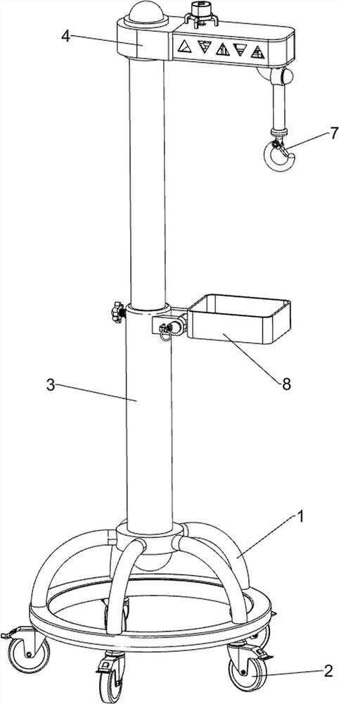
[0033] A shaker for insulin titration, such as figure 1 , image 3 and Figure 4 As shown, it includes a mounting frame 1, a pulley 2, a lifting mechanism 3 and a hanger assembly 4. The bottom of the mounting frame 1 is evenly spaced with a plurality of pulleys 2 along the circumferential direction. The mounting frame 1 is equipped with a lifting mechanism 3. The lifting mechanism A hanger assembly 4 is installed on the 3.
[0034] Lifting mechanism 3 comprises hollow post 31, threaded seat 32, screw rod 33 and knob 34, is connected with hollow post 31 in mounting frame 1, is connected with threaded seat 32 on hollow post 31 top, is connected with threaded mode in threaded seat 32. The screw rod 33 is connected with a knob 34 .
[0035] The hanger assembly 4 includes a support rod 41, a spacer 42, a mounting box 43 and a curved rod 44. The hollow column 31 is slidably connected with a support rod 41, and the upper part of the support rod 41 is rotatably connected with a spa...
Embodiment 2
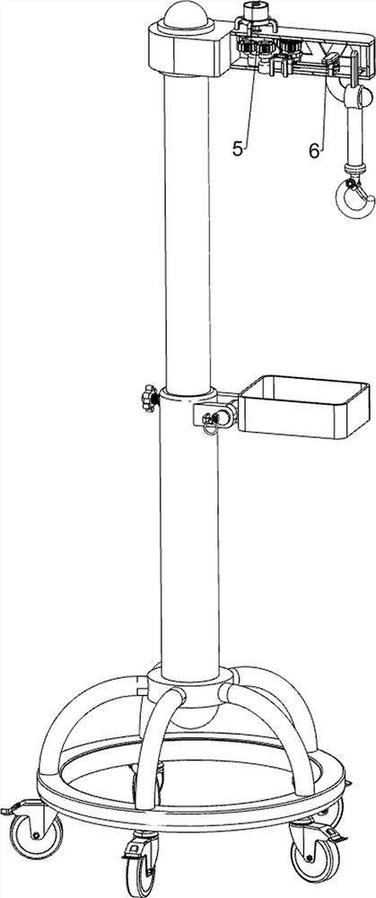
[0038] On the basis of Example 1, such as figure 2 , Figure 5 , Figure 6 and Figure 9As shown, a timing mechanism 5 is also included, and the timing mechanism 5 includes a first fixed frame 51, a servo motor 52, a sector gear 53, a first opposing gear set 54, a first one-way clutch 55, a first transmission shaft 56, Ratchet gear 57, first scroll spring 58, second fixed mount 59, block frame 510, second transmission shaft 511, protruding rod ring 512 and second opposing gear set 513, the top of installation box 43 is connected with the first fixed Frame 51, a servo motor 52 is installed on the first fixed frame 51, the output shaft of the servo motor 52 is connected with a sector gear 53 through a coupling, the sector gear 53 is located in the installation box 43, and the bottom of the installation box 43 is connected with a second Fixed frame 59, the first transmission shaft 56 is connected in rotation in the second fixed frame 59, the first scroll spring 58 is connecte...
Embodiment 3
[0042] On the basis of Example 2, such as figure 1 and Figure 7 As shown, a buckle mechanism 7 is also included, and the buckle mechanism 7 includes a fixed shaft 71, a second scroll spring 72 and a clamp frame 73, the bottom of the hook frame 67 is connected with a fixed shaft 71, and the fixed shaft 71 is rotationally connected There is a pallet frame 73 , and two second scroll springs 72 are connected between the pallet frame 73 and the fixed shaft 71 .
[0043] When the drop bottle is hung on the hook frame 67, turn the clip frame 73 upwards, the second scroll spring 72 is compressed thereupon, then the drop bottle can be hung on the hook frame 67, and then the clip frame 73 is released, Under the action of the second scroll spring 72, the clip frame 73 can be rotated downward and reset, and the drip bottle can be fixed on the hook frame 67 through the cooperation of the second scroll spring 72 and the clip frame 73, which can prevent dripping. The bottle falls when sha...
PUM
 Abstract
Description
Claims
Application Information
 - R&D
- Intellectual Property
- Life Sciences
- Materials
- Tech Scout
- Unparalleled Data Quality
- Higher Quality Content
- 60% Fewer Hallucinations
Browse by: Latest US Patents, China's latest patents, Technical Efficacy Thesaurus, Application Domain, Technology Topic, Popular Technical Reports.
© 2025 PatSnap. All rights reserved.Legal|Privacy policy|Modern Slavery Act Transparency Statement|Sitemap|About US| Contact US: help@patsnap.com


