Optical fiber mode field adapter with cladding power stripping function and preparation method thereof

A mode field adapter and cladding technology, applied in the directions of light guides, optics, instruments, etc., can solve the problems of damage to subsequent devices, damage to lasers, device influence, etc., and achieve the effect of reducing difficulty, reducing operating temperature, and reducing pressure

Inactive Publication Date: 2021-06-25
湖南大科激光有限公司
View PDF11 Cites 1 Cited by
  • Summary
  • Abstract
  • Description
  • Claims
  • Application Information

AI Technical Summary

Problems solved by technology

When the cladding light passes through the mode field adapter, part of it will be converted into heat, which will cause pressure on the device, and even cause the device to burn out and damage the laser
[0006] On the other hand, when the laser output from the previous stage enters the subsequent stage through the fiber mode field adapter, due to the influence of factors such as fusion splicing and processing technology, some core light will always enter the cladding of the output fiber. The devices of the subsequent stage will cause certain impact, and in severe cases, it will cause damage to the devices of the latter stage

Method used


Image

  • Optical fiber mode field adapter with cladding power stripping function and preparation method thereof
  • Optical fiber mode field adapter with cladding power stripping function and preparation method thereof
  • Optical fiber mode field adapter with cladding power stripping function and preparation method thereof

Examples


preparation example Construction

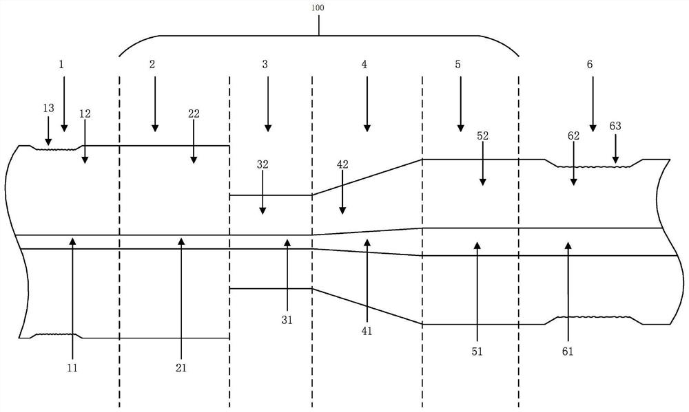
[0051] The present invention also provides a method for preparing an optical fiber mode field adapter with cladding power stripping function, comprising the following steps:

[0052] In the first step, the input optical fiber 2 and the output optical fiber 5 are prepared, wherein the core diameter of the output optical fiber 5 is greater than the core diameter of the input optical fiber 2;

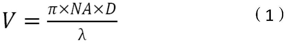
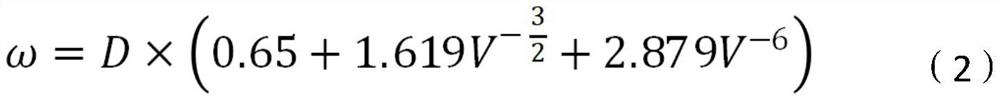
[0053] In the second step, according to the parameter requirements of the input optical fiber 2 and the output optical fiber 5, including the numerical aperture NA1 and the core diameter D1 of the input optical fiber 2, the numerical aperture NA2 and the core diameter D2 of the output optical fiber 5, and the operating wavelength λ of the device, by The following formula calculates the mode field diameter ω of the input fiber;

[0054]

[0055]

[0056] where NA is the numerical aperture of the fiber, V is the V value of the fiber, D is the core diameter, ω is the mode field diameter...

Embodiment 1

[0076] The core and cladding diameters of input fiber 2 are 10 μm and 130 μm, NA 0.075, and the core and cladding diameters of output fiber 5 are 25 μm and 400 μm, NA 0.065, respectively.

[0077] 1) Prepare the input optical fiber 2 and the output optical fiber 5, wherein the core diameter of the input optical fiber 2 is 10 μm, the cladding diameter of the input optical fiber is 130 μm, the core diameter of the output optical fiber 5 is 25 μm, and the cladding diameter of the output optical fiber is 400 μm. Strip off a section of the outer cladding of the input fiber 2 close to the end face of the fiber, the stripping length is not less than 10cm, and strip off a section of the outer cladding of the output fiber 5 near the middle position, the stripping length is not less than 20cm.

[0078] 2) The operating wavelength λ of the device is determined to be 1080nm, and the core diameter of the cone waist region 3 of the mode field adapter is calculated to be about 9.9 μm.

[007...

example 2

[0084] 1) The core and cladding diameters of input fiber 2 are 20 μm and 400 μm, NA0.065 respectively, and the core and cladding diameters of output fiber 5 are 25 μm and 400 μm, NA0.065. Strip off a section of the outer cladding of the input fiber 2 close to the end face of the fiber, the stripping length is not less than 10cm, and strip off a section of the outer cladding of the output fiber 5 near the middle position, the stripping length is not less than 20cm.

[0085] 2) The operating wavelength λ of the device is determined to be 1080 nm, and the core diameter of the tapered waist region 3 of the mode field adapter is calculated to be about 20 μm.

[0086]3) Under the condition of about 1400°C, heat the middle section of the output optical fiber 5 stripped of the outer cladding until it is melted, and then use an optical fiber fusion tapered machine to taper the melted output optical fiber 5, so that the mode field after tapered The core diameter of the tapered waist reg...


PUM

PropertyMeasurementUnit
lengthaaaaaaaaaa
lengthaaaaaaaaaa
diameteraaaaaaaaaa

Abstract

The invention provides an optical fiber mode field adapter with a cladding power stripping function and a preparation method thereof, the optical fiber mode field adapter comprises a fiber core mode field adaptation area and optical fiber cladding light stripping areas, and the optical fiber cladding light stripping areas are respectively arranged at the input end and the output end of the fiber core mode field adaptation area; according to the invention, the influence of cladding light on a fiber core mode field adaptation area is greatly reduced, and only the diameter of an input end optical fiber fundamental mode field is required to be smaller than that of an output end optical fiber fundamental mode field, so that the limitation of an optical fiber mode field adapter on the diameter of an optical fiber cladding is eliminated; and the mode field adapter with the input end optical fiber cladding diameter larger than the output end optical fiber cladding diameter becomes possible. According to the invention, the working temperature of a fusion point in the MFA can be reduced, the pressure of devices in front of and behind the MFA in the MOPA structure fiber laser is reduced, and the system stability is improved.

Description

technical field [0001] The invention relates to the field of fiber laser technology, in particular to an optical fiber mode field adapter with cladding power stripping function, and provides a preparation method of the optical fiber mode field adapter with cladding power stripping function. Background technique [0002] High-power fiber lasers are more and more widely used in industrial processing, photoelectric countermeasures and other fields. At present, the scheme of achieving high power and high beam quality output through the master oscillator power amplifier (MOPA) structure is widely used. The initial laser seed source of the laser is output in a single-mode or quasi-single-mode, which is amplified in a fiber with a larger core size in the subsequent stage to reduce the influence of nonlinear effects and obtain higher power. [0003] In the amplification system, in order to solve the problem of splicing loss of fibers with different mode field diameters, a fiber mode...

Claims


Application Information

Patent Timeline
Patent Type & Authority Applications(China)
IPC IPC(8): G02B6/245G02B6/255
CPCG02B6/245G02B6/255
Inventor 彭杨郭少锋赵成海
Owner 湖南大科激光有限公司
Why Eureka
Try Eureka