
Bent board card function test clamp and device

A function test, board technology, applied in the direction of measuring device, measuring device shell, printed circuit test, etc., can solve the problems of damage to the board under test, inconvenient pressing down of the device, increase of design cost, etc., to reduce the design cost and maintenance costs, reducing design and manufacturing costs, and improving the overall reuse rate

Active Publication Date: 2021-06-25
P&R MEASUREMENT INC
View PDF1 Cites 3 Cited by
  • Summary
  • Abstract
  • Description
  • Claims
  • Application Information

AI Technical Summary

Problems solved by technology

[0004] 1. Due to the use of multiple push-down drive structures at different angles, the structure of this type of curved board testing machine is very complicated, which increases the design cost and maintenance cost;
[0005] 2. Due to the use of multiple push-down drive structures at different angles, it is difficult to realize that the probes of different push-down drive structures contact the board under test at the same time, causing local force synchronization, pulling the board under test, and damaging the board under test Card;
[0006] 3. Due to the use of multiple push-down drive structures at different angles, the overall structure will vary greatly due to different tested boards, which is not conducive to standardized structural design, and is not conducive to the reuse of old parts and modules. Group control cost
The above technical solution provides a middle board clamping structure. If it is applied to the bending board test, it can be used to clamp the unilateral structure of the bending side, but this does not solve the problem of signal transfer. At the same time, in the whole testing machine It is not convenient to place, nor is it convenient for the pressing device to press down, so further improvement is needed

Method used


Image

  • Bent board card function test clamp and device
  • Bent board card function test clamp and device
  • Bent board card function test clamp and device

Examples


Embodiment Construction

[0053] In the description of the present invention, it should be understood that the orientation or positional relationship indicated by the terms "above", "below", "upper", "lower", "upper", "lower" etc. Orientation or positional relationship.

[0054] The idea, specific structure and technical effects of the present invention will be clearly and completely described below in conjunction with the embodiments and accompanying drawings, so as to fully understand the purpose, scheme and effect of the present invention. It should be noted that, in the case of no conflict, features in the embodiments of the present application may be combined with each other.

[0055] It should also be noted that, in the description of the present invention, unless otherwise clearly stipulated and limited, the terms "setting", "installation", "connection", "connection" and the like should be understood in a broad sense, for example, it may be a fixed connection , can also be detachably connected,...


PUM


Abstract

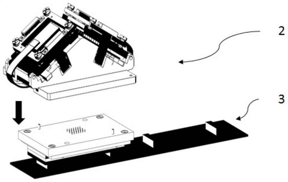
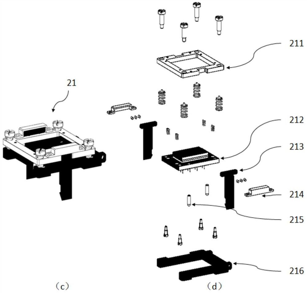
The invention discloses a bent board card function test fixture and device. The bent board card function test fixture comprises a clamping module and a carrier plate module. The clamping module is placed on the upper surface of the carrier plate module. The clamping module comprises a flip module and a board card holder. The shape of the upper surface of the board card holder is consistent with that of a bent board card. A needle block module is arranged in the flip module, and one end of the needle block module is hinged to the board card holder. The carrier plate module comprises a carrier plate. A needle plate is connected below the carrier plate in a floating manner, and carrier plate probes are arranged on the needle plate. The device further comprises a pressing plate module, a supporting module, an action control module, a vertical driving module, a horizontal driving module and a bottom plate. The bent board card function test clamp and device have the advantages that the balanced pressing action is realized through switching of the clamping module, and the structure is simplified; a double-layer signal switching structure is adopted, so that the probes can be prevented from being pulled; and meanwhile, the overall framework of a test machine can be designed into a standard framework, so that upgrading among different tested board cards is facilitated, and the standardized framework of the test machine is beneficial to reducing design and maintenance costs.

Description

technical field [0001] The invention relates to the technical field of board test devices, in particular to a bending type board function test fixture and device. Background technique [0002] With the rapid development of electronic product technology and the increasing requirements for process efficiency and yield, the electronics industry has gradually begun to strengthen the development and optimization of product functional testing equipment while improving the process efficiency of electronic products. Among them, the demand for functional testing (FCT) of electronic product motherboards is the most urgent. [0003] Common FCT testing machines are mainly used to test flat boards, while the research and development of FCT testing machines for curved boards is lagging behind. For the FCT testing machine of curved boards, the traditional structure is to install the needle plate module on the pressure plate module, and use multiple cylinders to drive the pressure plate mo...

Claims


Application Information

Patent Timeline
IPC IPC(8): G01R31/28G01R1/04
CPCG01R31/2806G01R31/2803G01R31/2815G01R1/0408
Inventor 莫宗杰沈小林杨兴华曾红钦王飞
Owner P&R MEASUREMENT INC
Learn More