Sampling equipment and sampling method for wine brewing wastewater treatment

A technology for sampling equipment and wastewater treatment, applied in sampling devices and other directions, can solve the problems of secondary treatment, reduce work efficiency, waste energy, etc., and achieve the effects of preventing impurity precipitation, improving service life, and improving accuracy

Pending Publication Date: 2021-06-25
浙江环森环境科技有限公司
View PDF0 Cites 0 Cited by
  • Summary
  • Abstract
  • Description
  • Claims
  • Application Information

AI Technical Summary

Problems solved by technology

[0003] The object of the present invention is to provide a sampling device and a sampling method for wine brewing wastewater treatment, equipped with an impeller in the waste water pipe, the impeller can be driven to rotate by the water flow, and the sample can be sampled through the impeller transmission, which saves energy and reduces the cost of the enterprise. Production cost, and through the rotation of the impeller, the stirring plate in the water tank is driven to continue to stir, which improves the purity of the sampling, and the waste water at different depths can be sampled by setting the moving tube, which improves the accuracy of the measured data and solves the current problem. Most of the sampling equipment is driven by electricity, which wastes energy and increases the production cost of the enterprise. Moreover, the purity of the sampling is not high enough, and most of them can only sample the water level at a fixed depth, resulting in inaccurate data and great impact on subsequent processing. Troublesome, easy to cause secondary processing and reduce work efficiency

Method used


Image

  • Sampling equipment and sampling method for wine brewing wastewater treatment
  • Sampling equipment and sampling method for wine brewing wastewater treatment
  • Sampling equipment and sampling method for wine brewing wastewater treatment

Examples


Embodiment Construction

[0027] The following will clearly and completely describe the technical solutions in the embodiments of the present invention with reference to the accompanying drawings in the embodiments of the present invention. Obviously, the described embodiments are only some, not all, embodiments of the present invention. Based on the embodiments of the present invention, all other embodiments obtained by persons of ordinary skill in the art without making creative efforts belong to the protection scope of the present invention.

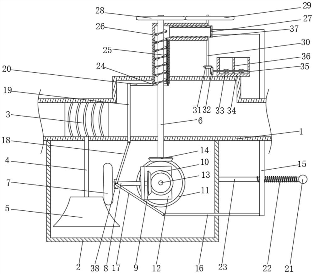
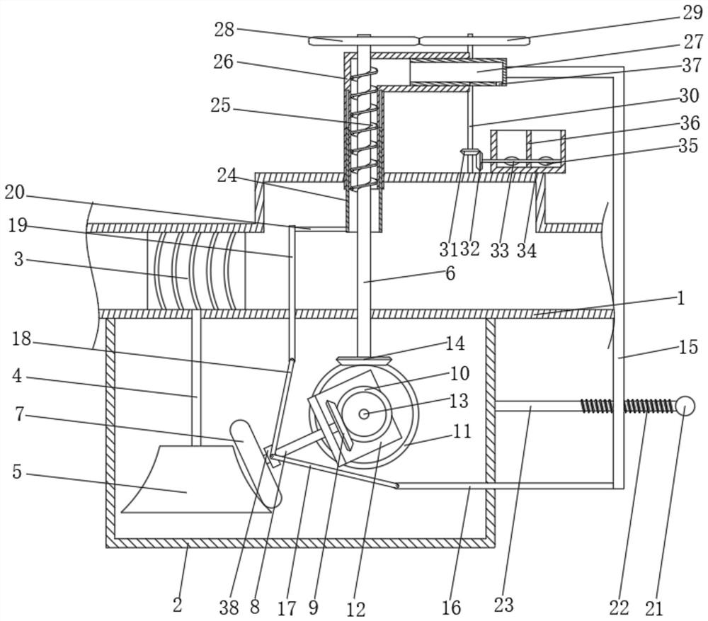
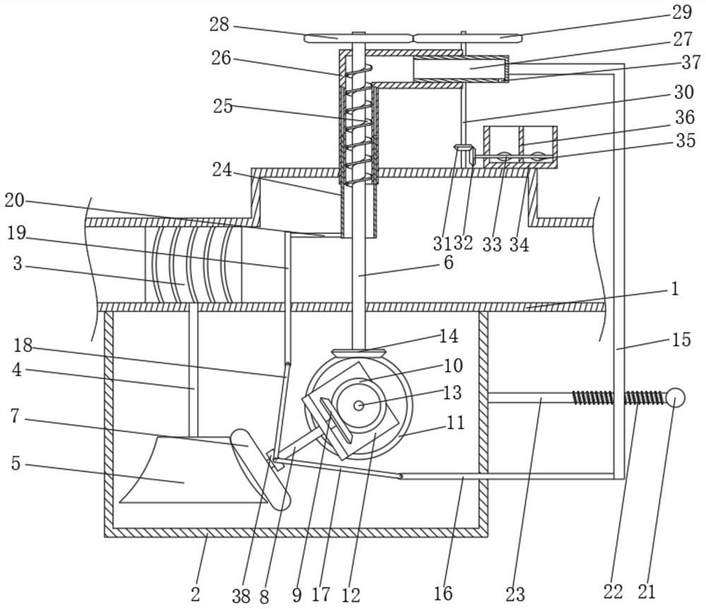
[0028] see Figure 1 to Figure 6 , the present invention provides a technical solution: a sampling device for brewing wastewater treatment, including a wastewater flow pipe 1 and a box body 2, and also includes an impeller 3, a rotating shaft 2 6 and a moving tube 24, and the impeller 3 is connected to the wastewater The inner wall of the circulation pipe 1 and the lower surface of the impeller 3 are fixedly connected with the rotating shaft 14, and the lower ...


PUM


Abstract

The invention discloses sampling equipment and a sampling method for wine brewing wastewater treatment, and relates to the technical field of wastewater sampling. The sampling equipment comprises a wastewater circulating pipe and a box body, and further comprises an impeller, a rotating shaft II and a moving pipe. The lower surface of the impeller is fixedly connected with a rotating shaft I, and the lower end of the rotating shaft I is fixedly connected with a conical friction wheel. The upper surface of the wastewater circulating pipe is fixedly communicated with an L-shaped pipe. The surface of the rotating shaft II is fixedly connected with a spiral plate. A wastewater collecting device is arranged on the wastewater circulating pipe. A transmission mechanism I for driving a moving pipe to move is arranged on the box body, and a transmission mechanism II is arranged in the box body. The problems that most of existing sampling equipment is driven by electric power, energy is wasted, the production cost of enterprises is increased, the sampling purity is not high enough, most of the sampling equipment can only sample water at fixed depth, data is not accurate, follow-up treatment is troublesome, secondary treatment is easily caused, and the working efficiency is reduced are solved.

Description

technical field [0001] The invention relates to the technical field of wastewater sampling, in particular to a sampling device and a sampling method for brewing wastewater treatment. Background technique [0002] A large amount of wastewater will be generated in the brewing process, which needs to be sampled and collected before centralized treatment to provide reference for subsequent production, but most of the existing sampling equipment is driven by electricity, which wastes energy and increases the Production costs, and the purity of sampling is not high enough, and most of them can only sample the water level at a fixed depth, resulting in inaccurate data, causing greater trouble for subsequent processing, easily causing secondary processing, and reducing work efficiency. Contents of the invention [0003] The object of the present invention is to provide a sampling device and a sampling method for wine brewing wastewater treatment, equipped with an impeller in the w...

Claims


Application Information

Patent Timeline
IPC IPC(8): G01N1/10
CPCG01N1/10Y02W10/10
Inventor 黄国梁蔡战林熊伟
Owner 浙江环森环境科技有限公司
Why Eureka
Try Eureka