Floating type cooling tower anti-overflow device and water collecting tray with same

A cooling tower and anti-overflow technology, which is applied to water shower coolers, direct contact heat exchangers, heat exchanger types, etc., can solve the problems of complicated anti-overflow process, troublesome manufacture, and complex structure of anti-overflow devices, etc. problem, to achieve the effect of simple and reliable anti-overflow operation and process, simple structure and improved protection effect

Pending Publication Date: 2021-06-25
HEFEI INSTITUTES OF PHYSICAL SCIENCE - CHINESE ACAD OF SCI
View PDF1 Cites 0 Cited by
  • Summary
  • Abstract
  • Description
  • Claims
  • Application Information

AI Technical Summary

Problems solved by technology

[0006] However, the anti-overflow device of this patent document has a complex structure, is troublesome to manufacture, and the anti-overflow process is complicated

Method used


Image

  • Floating type cooling tower anti-overflow device and water collecting tray with same
  • Floating type cooling tower anti-overflow device and water collecting tray with same
  • Floating type cooling tower anti-overflow device and water collecting tray with same

Examples


Embodiment 1

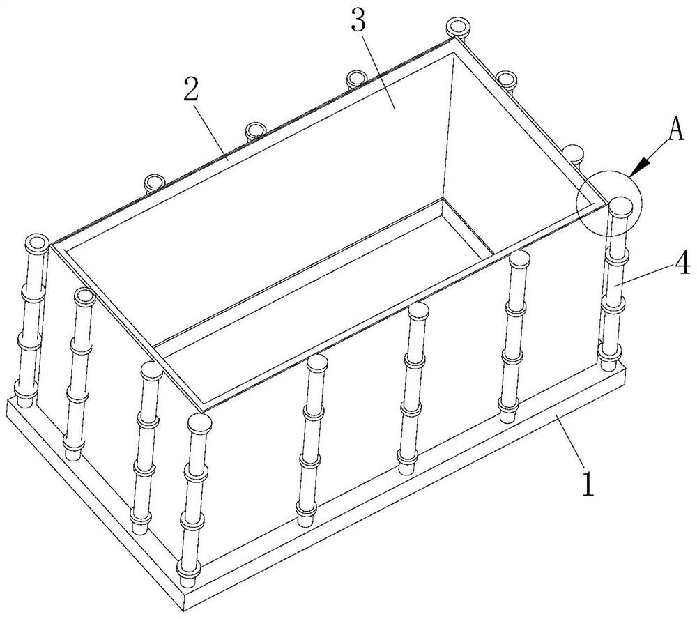
[0043] refer to figure 1 , the present embodiment discloses a floating cooling tower anti-overflow device, including a fence base 1, a floating frame 2, a stretchable waterproof cloth 3 and a strip stretching assembly 4.

[0044] The fence base 1 is a "mouth"-shaped structure surrounded by four square tubes. And the fence base 1 is fixed on the bottom of the water collecting pan in the cooling tower by bolts or clips or welding. A floating frame 2 is arranged above the fence base 1 .

[0045] refer to Figure 4 , the floating frame 2 is a "mouth"-shaped structure surrounded by four round tubes. And the overall length and width of the floating frame 2 is slightly smaller than the overall length and width of the fence base 1 . The floating frame 2 is a structure that is lightweight and can float on the water surface when encountering water. When the water surface is flush with the bottom surface of the floating frame 2, the bottom surface of the floating frame 2 is in cont...

Embodiment 2

[0053] refer to Figure 6 The difference between the second embodiment and the first embodiment is that the cloth strip stretching assembly 4 includes a bottom cylinder 404, a first stop ring 405, a first slider 406, a second stop ring 407, a second slider 408 , the third limiting ring 409 , the third sliding cylinder 410 and the top connecting block 403 . The number of the bottom cylinders 404 is four, and they are respectively arranged at the four corners of the top surface of the fence base 1 . And the bottom cylinder 404 is arranged outside the stretchable water-proof cloth 3 .

[0054] The top of the bottom cylinder 404 is welded with a first limiting ring 405 . The bottom cylinder 404 is sleeved with a first sliding cylinder 406 that can slide up and down inside the bottom cylinder 404 . The bottom of the first sliding cylinder 406 is welded with a first limiting block (not shown) that blocks each other with the first limiting ring 405 .

[0055] A second limiting ri...

Embodiment 3

[0063] The floating frame 2 is a square frame structure surrounded by driftwood. The floating effect of the floating frame 2 is improved to facilitate straightening the telescopic water barrier 3 when the liquid level of the water surface rises.


PUM


Abstract

The invention discloses a floating type cooling tower anti-overflow device. A light floating frame capable of floating on the water surface when meeting water is arranged above a fence base. When the water surface is flush with the bottom face of the floating frame, the bottom face of the floating frame is in contact with the water surface. The fence base is connected with the vertically corresponding pairwise frame edges of the floating frame through a telescopic waterproof cloth which surrounds the center of the floating frame by a circle. Cloth strip stretching assemblies for bearing the inward water pressure of the inner side of the telescopic waterproof cloth are arranged at the four corners outside the telescopic waterproof cloth. The top end of the telescopic waterproof cloth adheres to the movable end of the cloth strip stretching assembly. The top end of the telescopic waterproof cloth moves in the height direction of the cloth strip stretching assembly. According to the floating type cooling tower anti-overflow device, overflowing water is prevented from corroding a bearing platform, the dryness of the bearing platform can be kept, and the protection effect on the bearing platform is improved. The overflow phenomenon caused by the out-of-level bearing platform is weakened. The structure is simple, and anti-overflow operation is easy and reliable.

Description

technical field [0001] The invention relates to the technical field of anti-overflow of cooling towers, in particular to an anti-overflow device of a floating cooling tower and a water collecting tray provided with the device. Background technique [0002] The operation of the chiller is inseparable from the cooling water circulation. The heat dissipation equipment of the cooling water circulation is the cooling tower. The tower needs to be placed on the carrying platform. During the use of the cooling tower, the water level in the water collecting pan is controlled by controlling the float valve. [0003] Because the control accuracy of the float valve is very limited, and the base of the cooling tower is installed on the bearing platform, such as the roof, it is difficult to strictly adjust the level. During the operation, it often happens that when the cooling tower stops running, water overflows along the overflow hole, or even overflows along the outer eaves of the wat...

Claims


Application Information

Patent Timeline
IPC IPC(8): F28F25/04F28F25/00F28C1/00
CPCF28C1/00F28F25/00F28F25/04
Inventor 石玉洋唐佳丽欧阳峥嵘
Owner HEFEI INSTITUTES OF PHYSICAL SCIENCE - CHINESE ACAD OF SCI
Why Eureka
Try Eureka