
Internal circulation type grain drying equipment

A drying equipment and internal circulation technology, which is applied in the field of grain processing, can solve the problems of low drying efficiency and affecting drying efficiency, so as to increase drying capacity, increase drying efficiency, increase drying efficiency and drying capacity Effect

Inactive Publication Date: 2021-06-25
霍山知行信息科技有限公司
View PDF0 Cites 0 Cited by
  • Summary
  • Abstract
  • Description
  • Claims
  • Application Information

AI Technical Summary

Problems solved by technology

[0002] Grain drying is an important grain storage and transportation process. It is used to dry wet grain, which is convenient for grain transportation and long-term storage. The existing grain drying is usually processed by grain drying towers, and the grain is passed through the external pipeline. It is transported to the top of the grain drying tower, gradually falls through the inner cavity of the grain drying tower, and is dried by hot air, and then circulated and dried through the external conveying pipeline. Therefore, the grain drying efficiency depends on the grain drying efficiency. The overall time of the flow in the drying tower causes the existing equipment to affect the drying efficiency, and it is necessary to calculate the amount of grain to be dried each time, and the amount of added grain will also have certain limitations. A large amount of added grain will lead to accumulation , the hot air cannot fully contact with the grain, resulting in low drying efficiency

Method used


Image

  • Internal circulation type grain drying equipment
  • Internal circulation type grain drying equipment
  • Internal circulation type grain drying equipment

Examples


Embodiment Construction

[0030] The following will clearly and completely describe the technical solutions in the embodiments of the present invention with reference to the accompanying drawings in the embodiments of the present invention. Obviously, the described embodiments are only some, not all, embodiments of the present invention. Based on the embodiments of the present invention, all other embodiments obtained by persons of ordinary skill in the art without making creative efforts belong to the protection scope of the present invention.

[0031] In the description of the present invention, it should be noted that the orientation or positional relationship indicated by the terms "vertical", "upper", "lower" and "horizontal" are based on the orientation or positional relationship shown in the drawings, and are only for It is convenient to describe the present invention and simplify the description, but does not indicate or imply that the device or element referred to must have a specific orientati...


PUM


Abstract

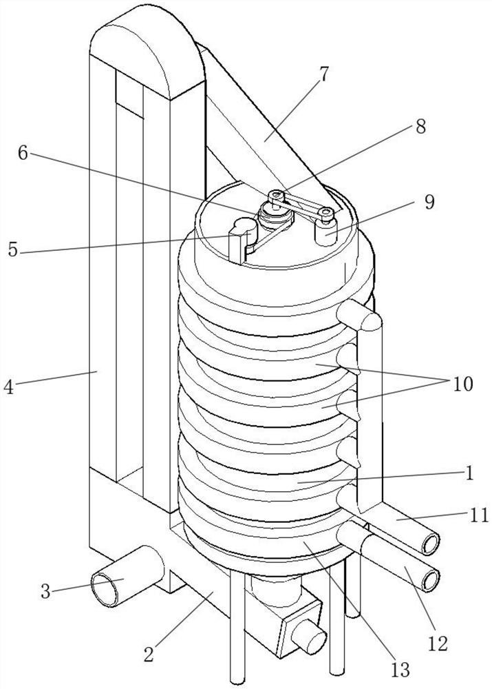
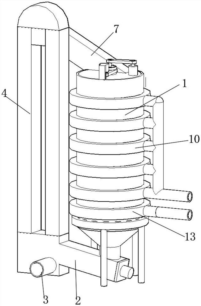
The invention discloses internal circulation type grain drying equipment. The internal circulation type grain drying equipment comprises a drying mechanism and an outer conveying mechanism. The drying mechanism comprises a drying tower, multiple layers of circulating screen plates are arranged in an inner cavity of the drying tower, each circulating screen plate is of a circular-truncated-cone-shaped structure, and a collecting screen plate is arranged below each layer of circulating screen plate. A collecting opening is formed in the position, located on the corresponding collecting screen plate, of an inner circulating pipe, and the bottom of each collecting opening extends to the position above the corresponding circulating screen plate. The outer conveying mechanism comprises a feeding channel, and the bottom of the feeding channel communicates with the bottom of the drying tower through a second conveying channel. According to the internal circulation type grain drying equipment, mesh gaps in the circulating screen plates and the collecting screen plates which are alternately arranged in multiple layers are gradually scattered, fall down and make full contact with hot air, circulating feeding is conducted in the drying tower, the drying efficiency is improved, the drying amount is increased, the production cost is effectively reduced, grains falling off onto the bottom are subjected to circulating feeding and multiple times of drying through the feeding channel, and the efficiency is improved.

Description

technical field [0001] The invention relates to the technical field of grain processing, in particular to an internal circulation type grain drying equipment. Background technique [0002] Grain drying is an important grain storage and transportation process. It is used to dry wet grain, which is convenient for grain transportation and long-term storage. The existing grain drying is usually processed by grain drying towers, and the grain is passed through the external pipeline. It is transported to the top of the grain drying tower, gradually falls through the inner cavity of the grain drying tower, and is dried by hot air, and then circulated and dried through the external conveying pipeline. Therefore, the grain drying efficiency depends on the grain drying efficiency. The overall time of the flow in the drying tower causes the existing equipment to affect the drying efficiency, and it is necessary to calculate the amount of grain to be dried each time, and the amount of a...

Claims


Application Information

Patent Timeline
Patent Type & Authority Applications(China)
IPC IPC(8): F26B17/00F26B21/00F26B25/00F26B25/02F26B25/04
CPCF26B17/002F26B17/003F26B21/004F26B25/00F26B25/002F26B25/02F26B25/04F26B2200/06
Inventor 张厚玉鲁晓飞
Owner 霍山知行信息科技有限公司
Learn More