
Pintle injector achieving head cooling through jet flow self-impact type membrane

A technology of injector and self-impact, which is applied in the direction of jet propulsion device, machine/engine, rocket engine device, etc. It can solve the problems of high cooling cost, only one-time use, complicated processing, etc., and achieve low processing cost and repeated High usability, improve the effect of atomization and mixing

Active Publication Date: 2021-06-25
XIAN AEROSPACE PROPULSION INST
View PDF6 Cites 1 Cited by
  • Summary
  • Abstract
  • Description
  • Claims
  • Application Information

AI Technical Summary

Problems solved by technology

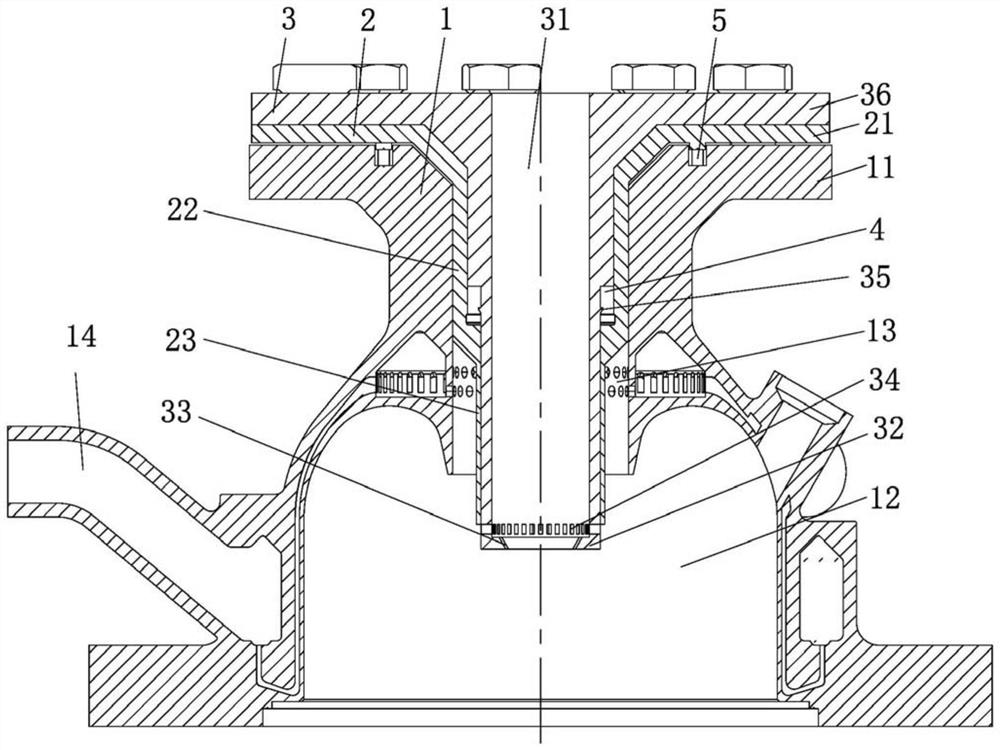
[0004] The purpose of the present invention is to solve the problems of complex processing, high cooling cost and single use of the existing pintle injector cooling method, and to provide a pintle injector that realizes head cooling through a jet self-impact film device

Method used


Image

  • Pintle injector achieving head cooling through jet flow self-impact type membrane
  • Pintle injector achieving head cooling through jet flow self-impact type membrane
  • Pintle injector achieving head cooling through jet flow self-impact type membrane

Examples


Embodiment Construction

[0024] The content of the present invention will be further described in detail below in conjunction with the accompanying drawings and specific embodiments.

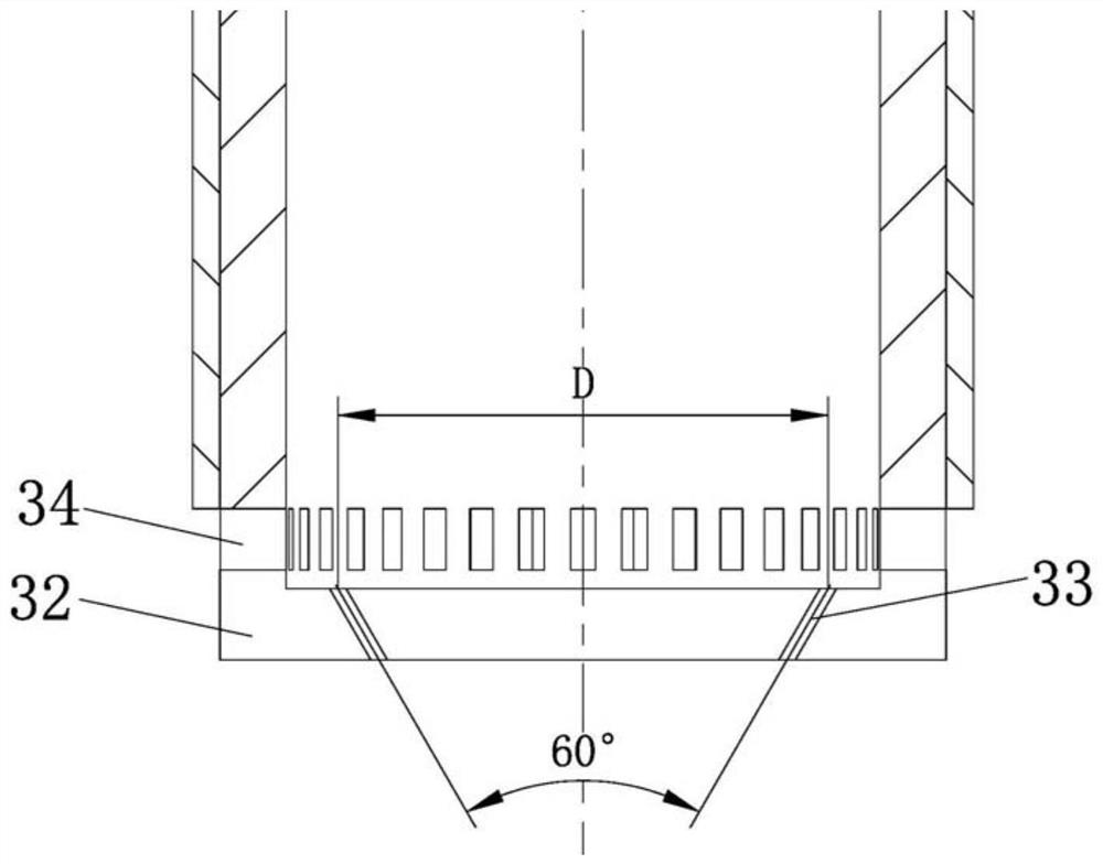
[0025] The present invention provides a needle pintle injector which realizes cooling of the head through jet self-impact film. A reliable way to achieve cooling of the pintle injector head. The cooling structure of the pintle injector of the present invention is mainly composed of a central cylinder and a number of impact holes connected with the inner cavity of the central cylinder. The jet formed by the hole hits a point at a certain distance from the head of the pintle injector, and a conical liquid film is formed at the point of impact. The jet and liquid film can make the pintle head and the returning high-temperature gas in the combustion chamber generate a certain At the same time, after the liquid film is broken, it evaporates and absorbs heat to reduce the temperature near the pintle head, protecting the pint...


PUM


Abstract

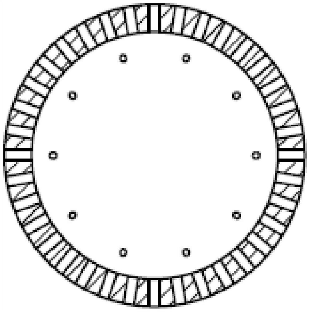
The invention provides a pintle injector achieving head cooling through a jet flow self-impact type membrane, and the problems that according to an existing pintle injector cooling mode, machining is complex, the cooling cost is high, and the cooling mode only can be used for one time are solved. The pintle injector comprises a combustion chamber, a needle valve and a central cylinder. The needle valve is arranged in a center channel of the combustion chamber and comprises a needle valve upper end cover and a needle valve lower barrel, wherein the needle valve upper end cover is arranged on the top of a combustion upper end cover, the needle valve lower barrel comprises a first barrel and a second barrel, and an annular propellant flow channel is arranged between the outer wall surface of the second barrel and the inner wall surface of the center channel of the combustion chamber and communicates with a liquid inlet of the combustion chamber. The central cylinder is arranged in an inner cavity of the needle valve, an open inner cavity liquid inlet is formed in the upper end of the central cylinder, and an inner end cover is arranged at the lower end of the central cylinder. A plurality of impact holes which communicate with an inner cavity of the central cylinder and have the same length-diameter ratio are formed in the inner end cover. A plurality of injection openings are formed in the lower end of the central cylinder in the circumferential direction of the central cylinder.

Description

technical field [0001] The invention belongs to the technical field of liquid rocket engine propellants, and in particular relates to a pintle injector which realizes head cooling through a jet self-impact membrane. Background technique [0002] The pintle injector is an important part of the liquid rocket engine. Compared with the traditional two-component impact or coaxial nozzle, the pintle injector can produce high combustion efficiency. And has the following working characteristics: strong adjustment ability, surface shutdown characteristics, low cost, high reliability, etc. [0003] Existing pintle injectors are cooled by active cooling methods (such as sweating cooling) or passive coating of anti-ablation coatings. However, sweating cooling methods have the disadvantages of complex processing and high cooling costs; The cooling method of the ablation coating cannot sufficiently cool the pintle injector, and the anti-ablation coating needs to be replaced after ablatio...

Claims


Application Information

Patent Timeline
Patent Type & Authority Applications(China)
IPC IPC(8): F02K9/52
CPCF02K9/52
Inventor 周康陈宏玉刘占一周晨初王丹李舒欣王勇
Owner XIAN AEROSPACE PROPULSION INST
Learn More