
Water retention and pressure relief device and method suitable for deep water level drilling ground stress test

A pressure relief device and ground stress technology, which is applied in the directions of surveying, earthwork drilling, and mining fluids, etc., can solve the problems of ultra-high water level drilling during the test time, long occupation, low efficiency, etc., and reduce the risk of repeated drilling up and down , saving test time and improving test efficiency

Pending Publication Date: 2021-06-25
CHANGJIANG RIVER SCI RES INST CHANGJIANG WATER RESOURCES COMMISSION
View PDF0 Cites 2 Cited by
  • Summary
  • Abstract
  • Description
  • Claims
  • Application Information

AI Technical Summary

Problems solved by technology

The double-pipe method forms two pressure channels by connecting the slender high-pressure water pipe and the drill pipe outside the packer, which is suitable for shallow drilling tests and is complicated to operate
As the burial depth of underground engineering becomes larger and larger, geological boreholes with large burial depth and deep water level will generally exist. Generally, the single-pipe method is used for testing, but the pressure formed by the difference between the inner and outer water heads of the drill pipe during the process of injecting water into the drill pipe will increase. As a result, the packer is self-expanding and fixed on the hole wall and cannot be moved. Therefore, a supporting pressure relief device is required to relieve the pressure of the packer alone. However, the existing pressure relief method is relatively inefficient, and the test time required is far longer than that of high water level drilling.
[0003] At present, there are mainly two types of pressure relief methods with high operability: the first pressure relief method cannot be continuously tested after the packer pressure is removed, and the packer needs to be fully lifted by the drill pipe after a test section is completed. On the ground, restore the pressure relief device manually, and then connect the drill pipe again and lower it to the designated position through the winch of the drilling rig, and refill the drill pipe with water. This method of pressure relief is the least efficient, and a lot of time and manpower are spent in the repeated lifting process. The water injection stage before connecting and dismounting the drill pipe and testing; the second pressure relief method fine-tunes the stroke of the piston in the pressure relief device by precisely controlling the lifting and lowering of the drill pipe on the ground so that the water in the drill pipe flows into the borehole and reduces the pressure of the drill pipe. The water head difference between inside and outside can achieve the purpose of pressure relief of the packer. After the pressure relief, it can be hoisted by the drilling rig and placed in the next test position for continuous testing. However, water needs to be injected into the drill pipe again before the test. This pressure relief method is relatively The efficiency of the first method has been improved, and there is no need to repeatedly lift the drill pipe, but it still takes a long time for the drill pipe to release water and water injection before retesting during the pressure relief process
Although the above two methods achieve the purpose of pressure relief, the efficiency is very low, and the clean water resources at the test site are often scarce. Therefore, in order to save time, manpower and material resources, improve test efficiency, and reduce test costs, a method suitable for deep water level is invented. An efficient and easy-to-operate hydraulic fracturing in-situ stress testing device and method for drilling is of great significance

Method used


Image

  • Water retention and pressure relief device and method suitable for deep water level drilling ground stress test
  • Water retention and pressure relief device and method suitable for deep water level drilling ground stress test
  • Water retention and pressure relief device and method suitable for deep water level drilling ground stress test

Examples


Embodiment Construction

[0029] In order to make the purpose, technical solutions and advantages of the embodiments of the present invention clearer, the technical solutions in the embodiments of the present invention will be clearly and completely described below in conjunction with the drawings in the embodiments of the present invention. Obviously, the described embodiments It is a part of embodiments of the present invention, but not all embodiments. Based on the embodiments of the present invention, all other embodiments obtained by persons of ordinary skill in the art without making creative efforts belong to the protection scope of the present invention.

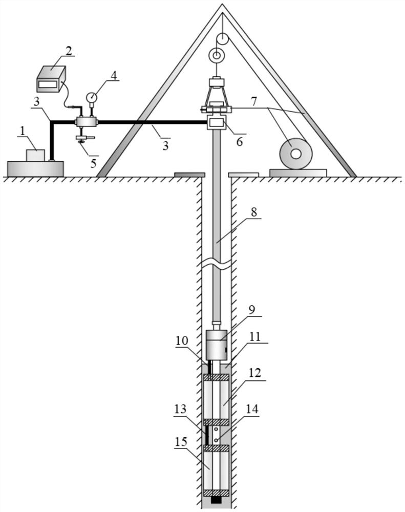
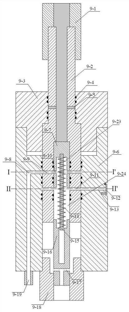
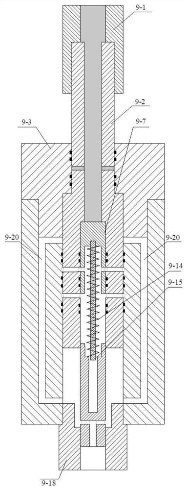
[0030] see figure 1 ~ Fig. 3, one embodiment of the water retention and pressure relief device suitable for deep-water level drilling in-situ stress testing according to the present invention, including a push-pull water retention and pressure relief device, an upper packer 12 and a lower packer located on the same vertical axis 15. The cent...


PUM


Abstract

The invention provides a water retention and pressure relief device and method suitable for a deep water level drilling ground stress test. The device comprises an upper packer, a lower packer and a push-pull water retention and pressure relief device body, wherein the upper packer and the lower packer are arranged in a drill hole, and the push-pull water retention and pressure relief device body is connected with a drill rod; the push-pull water retention and pressure relief device body comprises a body, a valve plug sliding cavity, a packer fluid channel, a pressure relief fluid channel, a center rod fluid channel and a push-pull valve plug, wherein the valve plug sliding cavity, the packer fluid channel, the pressure relief fluid channel and the center rod fluid channel are formed in the body, and the push-pull valve plug is connected with the drill rod and can move up and down in the valve plug sliding cavity; a built-in piston sliding cavity and a built-in piston capable of moving up and down in the built-in piston sliding cavity are arranged in the push-pull valve plug; a spring guide rod and a prestress spring arranged on the spring guide rod in a sleeving mode are arranged on the lower portion of the built-in piston; a piston limiter fixed to a center pipe connector is arranged below the spring guide rod; and the center pipe connector is connected with the center of the upper end of the upper packer. According to the water retention and pressure relief device and method, rapid pressure relief of the packers, storage of a drill rod water head and switching of pressure channels in the deep water level drilling ground stress test can be achieved, and the rapid and continuous ground stress test of deep water level drilling is further achieved.

Description

technical field [0001] The invention relates to the technical field of rock mass mechanics tests, in particular to a water retention and pressure relief device and method suitable for stress testing of deep-water drilling holes. Background technique [0002] Conventional hydraulic fracturing methods for in-situ stress testing are mainly divided into single-pipe method and double-pipe method. The single-pipe method realizes the pressure channel switching between the packer and the test section by connecting a push-pull valve between the drill pipe and the double-plug packer. It is suitable for continuous and rapid testing of deep drilling with high water level (generally the water level does not exceed 50m). easy to use. The double-pipe method forms two pressure channels by connecting a slender high-pressure water pipe and drill pipe outside the packer, which is suitable for shallow drilling tests and is complicated to operate. As the burial depth of underground engineering...

Claims


Application Information

Patent Timeline
IPC IPC(8): E21B47/00E21B47/06E21B43/26E21B33/122
CPCE21B47/00E21B47/06E21B43/26E21B33/122
Inventor 张新辉艾凯刘元坤付平韩晓玉董志宏李永松周春华尹健民周朝杜学才孙云卢文峰张恒罗文行房艳国李建贺王旺盛职承杰
Owner CHANGJIANG RIVER SCI RES INST CHANGJIANG WATER RESOURCES COMMISSION
Learn More