
Bridge steel structure prefabricated part manufacturing and machining machine and machining method

A technology for processing machinery and steel structures, applied in the direction of manufacturing tools, metal processing equipment, auxiliary devices, etc., can solve the problem of affecting the use effect, reducing the effect and efficiency of bridge steel structure prefabricated parts welding, and difficult to ensure the accuracy of steel plate components, etc. Problems, to improve the effect of welding, improve the effect of precision

Inactive Publication Date: 2021-06-25
高黎明
View PDF0 Cites 6 Cited by
  • Summary
  • Abstract
  • Description
  • Claims
  • Application Information

AI Technical Summary

Problems solved by technology

[0004] 1. After the welding of the upper end of the bridge steel structure prefabricated part is completed, it is difficult to flip the bridge steel structure prefabricated part to weld its backside, thereby reducing the effect and efficiency of welding the bridge steel structure prefabricated part;
[0005] 2. In the current process of welding bridge steel structure prefabricated parts, the smaller steel plate components are usually supported and fixed manually. However, it is difficult to ensure the accuracy of the angle and size of the welded steel plate components in this process, thus The effect of welding processing on bridge steel structure prefabricated parts is reduced, which affects its subsequent use effect

Method used


Image

  • Bridge steel structure prefabricated part manufacturing and machining machine and machining method
  • Bridge steel structure prefabricated part manufacturing and machining machine and machining method
  • Bridge steel structure prefabricated part manufacturing and machining machine and machining method

Examples


Embodiment Construction

[0038] In order to make the technical means, creative features, goals and effects achieved by the present invention easy to understand, the present invention will be further described below in conjunction with specific illustrations. It should be noted that, in the case of no conflict, the embodiments in the present application and the features in the embodiments can be combined with each other.

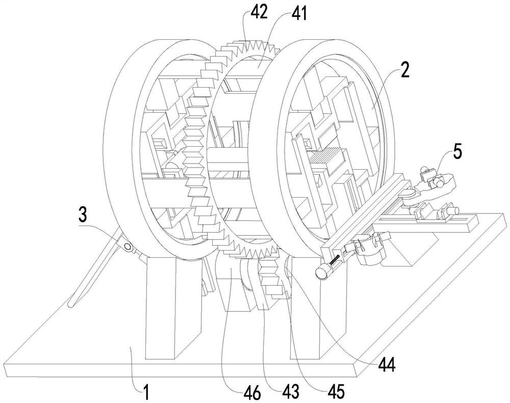
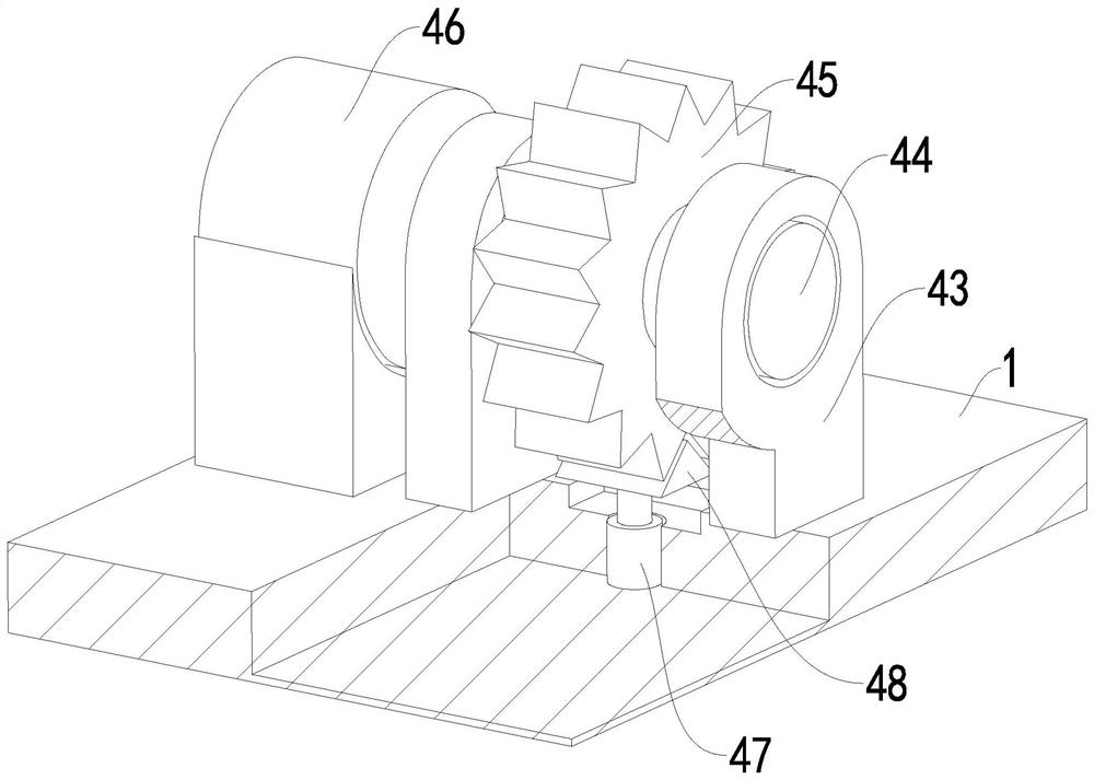
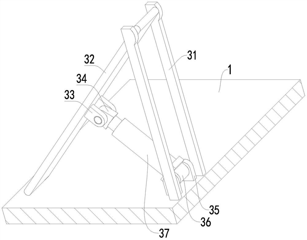
[0039] Such as Figure 1 to Figure 9 As shown, a bridge steel structure prefabricated production and processing machine includes a base 1, a clamping mechanism 2, a material lifting mechanism 3, a rotating mechanism 4 and a supporting mechanism 5, and the middle part of the upper end surface of the base 1 is symmetrically arranged with clips Holding mechanism 2, the left side of the holding mechanism 2 on the upper end surface of the base 1 is provided with a lifting mechanism 3, the holding mechanisms 2 are connected by a rotating mechanism 4, and the right side of the holding mecha...


PUM


Abstract

The invention relates to a bridge steel structure prefabricated part manufacturing and machining machine and machining method. The bridge steel structure prefabricated part manufacturing and machining machine comprises a base, clamping mechanisms, a material lifting mechanism, a rotating mechanism and a bearing mechanism, wherein the clamping mechanisms are arranged in the middle of the upper end face of the base in a bilateral symmetry manner, and the material lifting mechanism is arranged on the upper end face of the base and located at the left side of the clamping mechanism at the left side; and the clamping mechanisms are connected through the rotating mechanism, and the bearing mechanism is arranged at the right side of the clamping mechanism at the right side. The bridge steel structure prefabricated part manufacturing and machining machine and machining method solve the problems that in the prior art, in the process of splicing and welding bridge steel structure prefabricated parts on the ground in a manual manner: after welding of the upper ends of the bridge steel structure prefabricated parts is completed, the bridge steel structure prefabricated parts are difficult to turn over, and the back faces of the bridge steel structure prefabricated parts are difficult to weld; and small steel plate assemblies are held and fixed in a manual manner, the angle between the steel plate assemblies and the size accuracy degree are difficult to control in the process, and the welding machining effect on the bridge steel structure prefabricated parts is reduced.

Description

technical field [0001] The invention relates to the field of steel structure engineering, in particular to a manufacturing and processing machine and processing method for bridge steel structure prefabricated parts. Background technique [0002] Steel structure engineering is a structure mainly made of steel. It is mainly composed of steel beams, steel columns, steel trusses and other components made of steel and steel plates. The components or parts are usually connected by welds, bolts or rivets. One of the main types of building structures. Because of its light weight and easy construction, it is widely used in large-scale factories, bridges, venues, super high-rises and other fields. Among them, supporting steel beams are usually used in the steel structure engineering during bridge erection, and the prefabricated parts of supporting steel beams It is usually composed of: a, H-shaped steel; b, supporting steel plate with threaded holes for increasing the supporting area...

Claims


Application Information

Patent Timeline
IPC IPC(8): B23K37/047B23K31/02
CPCB23K31/02B23K37/047
Inventor 高黎明
Owner 高黎明
Learn More