Plastic tube hot-melting welding machine

A technology for plastic pipes and welding machines, applied in the field of plastics, can solve the problems of welding failure, defective products, and inability to heat at the same time.

Active Publication Date: 2019-11-15
YANCHENG RUITONG PLASTIC CO LTD
View PDF9 Cites 6 Cited by
  • Summary
  • Abstract
  • Description
  • Claims
  • Application Information

AI Technical Summary

Problems solved by technology

[0003] Plastic welding refers to the connection method that melts the contact surfaces of two plastic parts at the same time by heating, so that they are combined into a whole; at present, most of the welding between the nozzles of plastic pipes adopts the method of hot-melt butt joint of plastic pipes 1. Heat the welding interface of the two plastic pipes to a viscous state with a heating plate, then remove the heating plate; then manually apply opposing pressure to the two plastic pipes, and cool and solidify under this pressure state to form a firm connection; In the prior art, if the welding round holes on the two plastic pipes cannot be positioned accurately during the process of manual pressure, the welding will fail and cause defective products; and when using a heating plate that can only be heated on one side, The two plastic pipes cannot be heated at the same time. In this state, during butt welding, one of the two plastic pipes will be heated first. After the heating is completed, in the process of heating the other plastic pipe, if the time If it is too long, the previously heated plastic pipe will solidify, resulting in welding failure

Method used


Image

  • Plastic tube hot-melting welding machine
  • Plastic tube hot-melting welding machine
  • Plastic tube hot-melting welding machine

Examples


Embodiment Construction

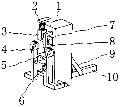
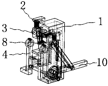
[0045] like figure 1 , 2 As shown, it includes installation shell 1, return spring 2, hot melt block 3, drive arm 4, limit plate 5, guide block 6, drive mechanism 7, trigger mechanism 8, drive swing rod 10, threaded rod 18, guide rod 12, guide groove 15, T-shaped slide block 31, drive plate 49, drive spring 19, slide block 20, wherein as Figure 7 As shown, there is a threaded hole 28 on the installation shell 1, such as Image 6 As shown, the threaded rod 18 is installed on the fixed shell through the threaded hole 28, and the two ends of the threaded rod 18 pass through the mounting shell 1 and are located on both sides of the mounting shell 1; Figure 5 As shown, one end of the driving arm 4 has a detachable fixing ring 11 for fixing the plastic pipe, and the other end of the driving arm 4 is installed on the two ends of the threaded rod 18 through screw fit; one side of the driving arm 4 is equipped with a guide rod 12, like Figure 4 As shown, there are two through gu...


PUM


Abstract

The invention belongs to the technical field of plastics, and particularly relates to a plastic tube hot-melting welding machine. The plastic tube hot-melting welding machine comprises a mounting shell, a return spring, a hot-melting block, driving arms, a limiting plate, a driving mechanism, a trigger mechanism and a driving swing rod. The plastic water tube welding machine firstly controls the driving swing rod to swing downward so that a fuser can heat two plastic tubes, and then controls the driving swing rod to swing upward so that the two driving arms can drive the plastic tubes to firstmove to both sides, and then the driving swing rod can swing upward to control the hot-melting block to move upward; when the hot-melting block is completely moved to the upper side, the driving swing rod is driven to swing downward again, and the driving swing rod swings to control the two driving arms to drive the plastic tubes to move, and finally the contact pressure is applied to weld the two plastic tubes together; the situation that tube openings cannot be aligned because the two plastic tubes are artificially stressed, the welding effect is influenced, and leakage of the welding is caused is reduced; and meanwhile, the situation that the welding effect is influenced due to the curing of originally heated plastic tubes due to two times of heating is prevented.

Description

[0001] Technical field [0002] The invention belongs to the technical field of plastics, in particular to a plastic pipe hot-melt welding machine. Background technique [0003] Plastic welding refers to the connection method that melts the contact surfaces of two plastic parts at the same time by heating, so that they are combined into a whole; at present, the welding between the nozzles of plastic pipes mostly adopts the method of hot-melt butt joint of plastic pipes 1. Heat the welding interface of the two plastic pipes to a viscous state with a heating plate, then remove the heating plate; then manually apply opposite pressure to the two plastic pipes, and cool and solidify under this pressure state to form a firm connection; In the prior art, if the welding round holes on the two plastic pipes cannot be positioned accurately during the manual pressure application, the welding will fail and cause defective products; and when using a heating plate that can only be heated on...

Claims


Application Information

Patent Timeline
Patent Type & Authority Applications(China)
IPC IPC(8): B29C65/20B29C65/78
CPCB29C65/20B29C65/7841B29C66/5221
Inventor 邱博
Owner YANCHENG RUITONG PLASTIC CO LTD
Why Eureka
Try Eureka