Plastic pipe hot melting welding machine

A hot-melt welding and plastic pipe technology, applied in the field of plastics, can solve the problems of plastic pipe solidification, inability to heat at the same time, welding failure, etc.

Inactive Publication Date: 2019-05-03
圣大管业科技股份有限公司
View PDF6 Cites 1 Cited by
  • Summary
  • Abstract
  • Description
  • Claims
  • Application Information

AI Technical Summary

Problems solved by technology

[0002] Plastic welding refers to the connection method that melts the contact surfaces of two plastic parts at the same time by heating, so that they are combined into a whole; at present, the welding between the nozzles of plastic pipes mostly adopts the method of hot-melt butt joint of plastic pipes 1. Heat the welding interface of the two plastic pipes to a viscous state with a heating plate, then remove the heating plate; then manually apply opposite pressure to the two plastic pipes, and cool and solidify under this pressure state to form a firm connection; In the prior art, if the welding round holes on the two plastic pipes cannot be positioned accurately during the manual pressure application, the welding will fail and cause defective products; and when using a heating plate that can only be heated on one side, The two plastic pipes cannot be heated at the same time. In this state, during butt welding, one of the two plastic pipes will be heated first. After the heating is completed, in the process of heating the other plastic pipe, if the time If it is too long, the previously heated plastic pipe will solidify, resulting in welding failure

Method used


Image

  • Plastic pipe hot melting welding machine
  • Plastic pipe hot melting welding machine
  • Plastic pipe hot melting welding machine

Examples


Embodiment Construction

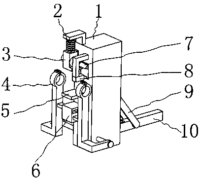
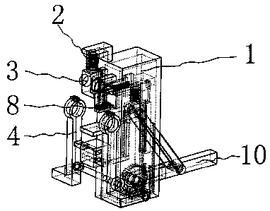
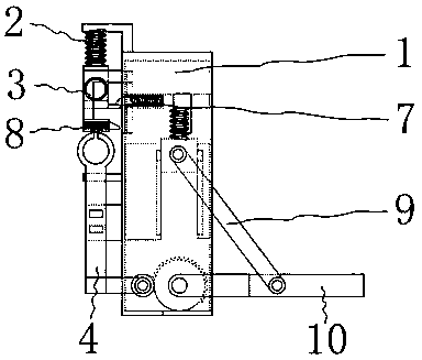
[0044] Such as figure 1 , 2 As shown, it includes installation shell 1, return spring 2, hot melt block 3, drive arm 4, limit plate 5, guide block 6, drive mechanism 7, trigger mechanism 8, drive swing rod 10, threaded rod 18, guide rod 12, guide groove 15, T-shaped slide block 31, drive plate 49, drive spring 19, slide block 20, wherein as Figure 7 As shown, there is a threaded hole 28 on the installation shell 1, such as Figure 6 As shown, the threaded rod 18 is installed on the fixed shell through the threaded hole 28, and the two ends of the threaded rod 18 pass through the mounting shell 1 and are located on both sides of the mounting shell 1; Figure 5 As shown, one end of the driving arm 4 has a detachable fixing ring 11 for fixing the plastic pipe, and the other end of the driving arm 4 is installed on the two ends of the threaded rod 18 through screw fit; one side of the driving arm 4 is equipped with a guide rod 12, Such as Figure 4 As shown, there are two thr...


PUM


Abstract

The invention belongs to the technical field of plastics, and particularly relates to a plastic pipe hot melting welding machine. The welding machine includes a mounting shell, a preset spring, a hotmelting block, driving arms, a limiting plate, a driving mechanism, a trigger mechanism and a driving swing rod, according to the plastic water pipe welding machine, firstly, the driving swing rod iscontrolled to swing downwards, thus two plastic pipes are heated through a hot melting machine, then the driving swing rod is controlled to swing upwards, thus the two driving arms firstly drive the plastic pipes to move away to the two sides, then the driving swing rod swings upwards to control the hot melting block to move upwards, after the hot melting block completely moves to the upper side,the driving swing rod is again driven to swing downwards, the two driving arms are controlled to drive the plastic pipes to move by driving the driving swing rod, and finally, the two plastic pipes are welded together through contact pressure adding. The phenomena that the welding effect is affected and the leakage openings are caused by welding due to the fact that pipe orifices cannot be aligneddue to manual pressure on the two plastic pipes are avoided; and meanwhile the phenomenon that welding effect is affected due to the fact that the plastic pipes heated originally is solidified due toheating for twice is prevented.

Description

Technical field [0001] The invention belongs to the technical field of plastics, in particular to a plastic pipe hot-melt welding machine. Background technique [0002] Plastic welding refers to the connection method that melts the contact surfaces of two plastic parts at the same time by heating, so that they are combined into a whole; at present, the welding between the nozzles of plastic pipes mostly adopts the method of hot-melt butt joint of plastic pipes 1. Heat the welding interface of the two plastic pipes to a viscous state with a heating plate, then remove the heating plate; then manually apply opposite pressure to the two plastic pipes, and cool and solidify under this pressure state to form a firm connection; In the prior art, if the welding round holes on the two plastic pipes cannot be positioned accurately during the manual pressure application, the welding will fail and cause defective products; and when using a heating plate that can only be heated on one si...

Claims


Application Information

Patent Timeline
IPC IPC(8): B29C65/20B29L23/00
CPCB29C65/20B29C65/7841B29C66/5221
Inventor 邱博
Owner 圣大管业科技股份有限公司
Why Eureka
Try Eureka