Chip flushing device

A technology of flushing device and chip, which is applied in the directions of drying gas arrangement, cleaning method using liquid, cleaning method and utensils, etc., can solve the problems of large amount of flushing liquid and gas, long operation time, inconsistent actual parameters, etc., to save flushing Liquid and gas, easy to operate and control, avoid the effect of liquid residue

Active Publication Date: 2021-08-10
捷仪科技(北京)有限公司
View PDF7 Cites 0 Cited by
  • Summary
  • Abstract
  • Description
  • Claims
  • Application Information

AI Technical Summary

Problems solved by technology

Manual operation is difficult to flush all sites at the same time, the actual parameters of each site flushing are inconsistent, and the effect of each flushing is also different
In addition, manual flushing also has disadvantages such as long operation time, low efficiency, and large amount of flushing fluid and gas consumed.
[0009] The other is immersion rinsing, which usually immerses chips or a batch of chips in the rinsing solution to achieve rinsing. Its disadvantage is that it is difficult to ensure that no contamination occurs during rinsing. Moreover, immersion rinsing is also difficult to rinse all positions at the same time. point, the actual parameters of flushing at each point are inconsistent, and the effect of each flushing cannot be guaranteed to be the same
[0010] The other is the automatic washing and drying mechanism disclosed in CN 206139560 U, CN 208146533 U, etc. When this type of mechanism is washing and drying the chip, the water flow and the air flow flow through the surface of the modified electrode, and the modified molecules attached to the electrode surface It has a certain destructive effect, and there is no design to prevent waste liquid from flowing through other sites. It is difficult to ensure that no pollution occurs during flushing, and it is difficult to ensure that all sites on the chip have the same flushing effect

Method used


Image

  • Chip flushing device
  • Chip flushing device
  • Chip flushing device

Examples


Embodiment Construction

[0040]In order to enable those skilled in the art to better understand the solution of the present invention, the present invention will be further described in detail below in conjunction with the accompanying drawings and specific embodiments.

[0041] In this article, terms such as "upper, lower, left, right" are established based on the positional relationship shown in the drawings, and the corresponding positional relationship may also change accordingly depending on the drawings. It is understood as an absolute limitation on the scope of protection; moreover, relative terms such as "first" and "second" are only used to distinguish one from another component with the same name, and do not necessarily require or No such actual relationship or order between these components is implied.

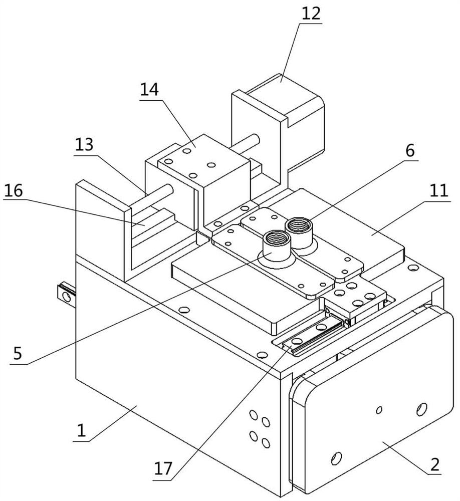
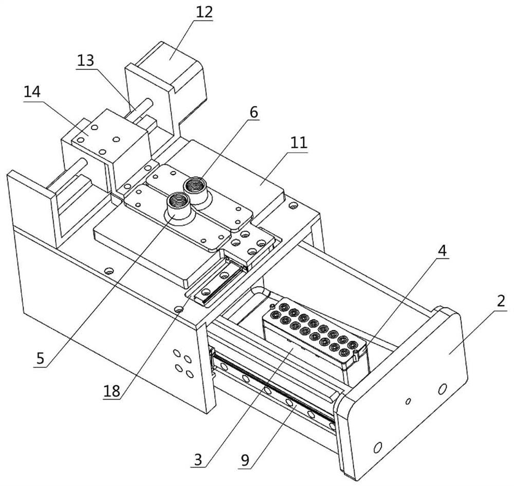
[0042] Please refer to figure 1 , figure 2 , figure 1 It is a structural schematic diagram of a chip flushing device disclosed in an embodiment of the present invention when the flushin...


PUM


Abstract

The invention discloses a chip flushing device, comprising an outer frame body and a flushing pool, the outer frame body has an inner cavity for accommodating the flushing pool, and the flushing pool is configured to be able to enter or exit the interior of the outer frame body cavity; the inside of the flushing pool is provided with a flushing platform, and the top of the flushing platform is used to load chips; the top of the outer frame is provided with a nozzle, and the nozzle includes a liquid nozzle for spraying flushing liquid on the surface of the chip and a gas spray head for blowing air to the surface of the chip; the rinse tank or spray head is provided with a position adjustment mechanism capable of driving it to move, and the position adjustment mechanism is used to adjust the relative position of the spray head and the rinse platform. The flushing device can flush all the points of the chip at the same time, ensuring that the actual parameters of each point flushing are consistent, and the effect of each flushing is the same. Its structure design is reasonable, easy to operate and control, and the operation efficiency is high, which can effectively save flushing liquid and gas. .

Description

technical field [0001] The invention relates to the technical field of chip washing equipment, in particular to a device for washing electrochemical analysis chips, biological detection chips, modified electrode chips and other chips. Background technique [0002] An electrochemical chip generally consists of a substrate and electrodes on it. The substrate is generally non-conductive glass, ceramics, plastics and other materials, and the electrodes on it are generally metal coatings. There are generally three areas on the electrochemical chip, electrode area, wire area and lead area. When in use, drop the liquid to be tested on the electrode area, and use the contact plate on the connector and chip lead area to derive the signal. [0003] An electrode area on a chip is generally composed of 2-4 electrodes, which is called a cell. In order to achieve high-throughput electrochemical analysis, multiple cells are often placed on an electrochemical chip, and each cell operates ...

Claims


Application Information

Patent Timeline
Patent Type & Authority Patents(China)
IPC IPC(8): B08B3/02B08B13/00F26B21/00
CPCB08B3/02B08B13/00F26B21/001
Inventor 黎敏清陆宜蔡渊
Owner 捷仪科技(北京)有限公司
Why Eureka
Try Eureka