Electric stapler with detachable power module and power module housing

A power module and stapler technology, applied in the field of medical devices, can solve problems such as inability to perceive force, inability to replace staple cartridges of different lengths, heavy burden on patients, etc., to avoid complications of sticky surgery, improve use safety, and reduce use. cost effect

Active Publication Date: 2022-06-24
BEIJING BIOSIS HEALING BIOLOGICAL TECH
View PDF5 Cites 0 Cited by
  • Summary
  • Abstract
  • Description
  • Claims
  • Application Information

AI Technical Summary

Problems solved by technology

In the prior art, electric staplers are all disposable, resulting in high cost of use and heavy burden on patients
The power source of the existing electric stapler is mainly the motor. Since the stapler is a one-time use, due to cost considerations, the quality of the selected motor is poor, resulting in a high risk of failure of the electric stapler.
[0003] Because the electric stapler is driven by a motor, it cannot sense the force used when cutting tissue and closing the tissue wound, so it cannot judge the thickness of the tissue or even the state of tissue lesions.
[0004] Depending on the actual situation, the electric stapler needs to have staple cartridges of different lengths, and the movement stroke of the firing rod is also different for staple cartridges of different lengths. The existing electric staplers are used with staple cartridges of a specific length and cannot be replaced. Staple cartridges of different lengths

Method used


Image

  • Electric stapler with detachable power module and power module housing
  • Electric stapler with detachable power module and power module housing
  • Electric stapler with detachable power module and power module housing

Examples


Embodiment Construction

[0115] Exemplary embodiments of the present invention are described below with reference to the accompanying drawings. It should be understood that these specific descriptions are only used to teach those skilled in the art how to implement the present invention, and are not used to exhaust all possible ways of the present invention, nor to limit the scope of the present invention.

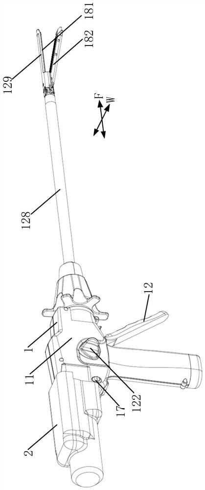
[0116] Unless otherwise specified, the anterior-posterior direction F refers to the anterior-posterior direction of the electric stapler, the front refers to the end that points to the patient when using the electric stapler, and the rear refers to the end that points to the operator when using the electric stapler; The left and right directions of the electric stapler, left refers to the operator's left side, and right refers to the operator's right side.

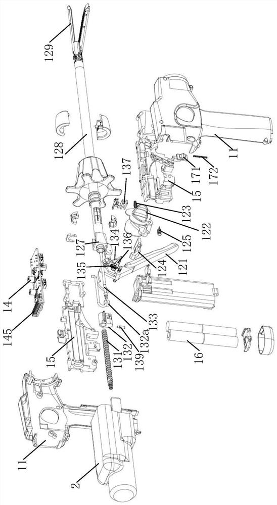
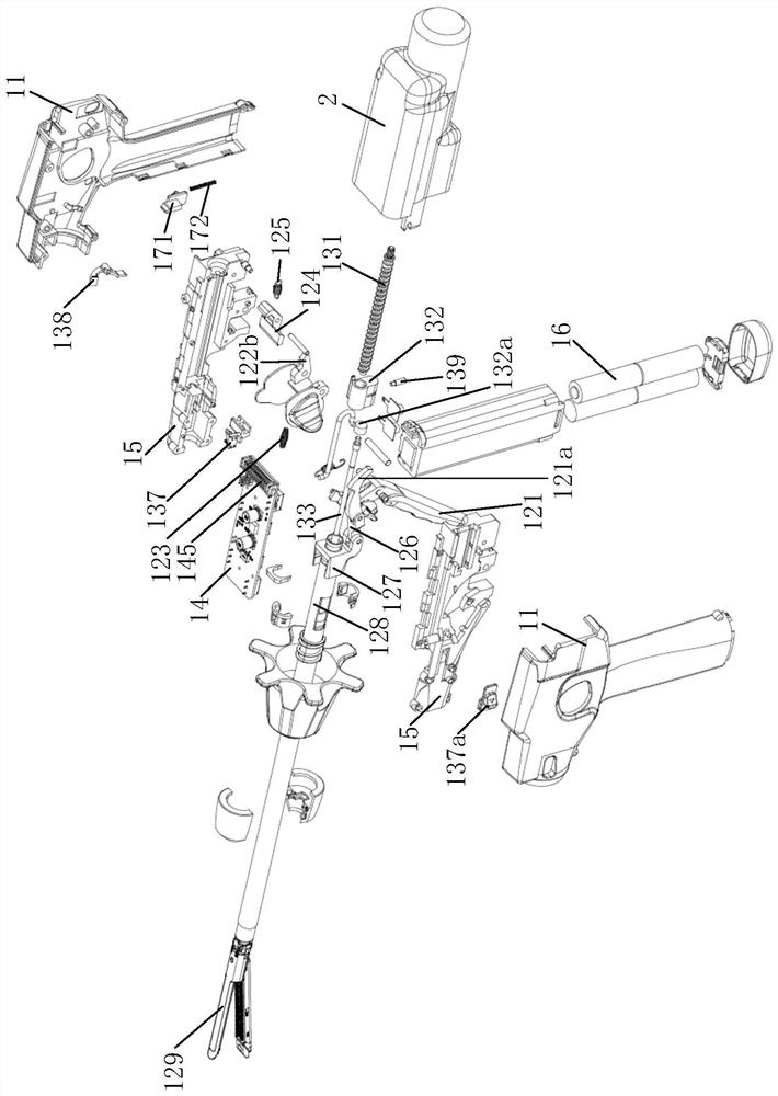
[0117] like Figure 1 to Figure 17 As shown, the present invention provides an electric stapler, which includes a main body 1 and a power mo...


PUM


Abstract

The present invention proposes an electric stapler with a detachable power module and a power module shell. The electric stapler includes: a main body capable of cutting tissue and firing staples to close the wound and stop bleeding. The main body is provided with Interface board; power module, the power module can be detachably connected to the main body, the power module includes a control unit, and the power module also includes a motor and / or battery assembly, between the main body and the power module When connected together, the control unit is electrically connected to the interface board. By adopting the above technical solution, at least one of the control unit and the motor and the battery of the electric stapler can be disassembled from the main body, and the disassembled part can be sterilized or replaced by a disposable sterile power module shell And be used repeatedly, thereby reduce the use cost of electric stapler.

Description

technical field [0001] The invention relates to the field of medical instruments, in particular to an intelligent electric drive surgical instrument, in particular to an intelligent electric stapler. Background technique [0002] Electric staplers are used in minimally invasive surgical procedures, which can cut diseased tissue and close wounds. In the prior art, all electric staplers are disposable, resulting in high use cost and heavy burden on patients. The power source of the existing electric stapler is mainly the motor. Since the stapler is one-time use, the selected motor is of poor quality due to cost considerations, resulting in a high risk of failure of the electric stapler. [0003] Because the electric stapler is driven by a motor, it cannot sense the force used when cutting tissue and closing tissue wounds, so it cannot judge the thickness of the tissue or even the pathological condition of the tissue. [0004] Depending on the actual situation, the electric s...

Claims


Application Information

Patent Timeline
Patent Type & Authority Patents(China)
IPC IPC(8): A61B17/072
CPCA61B17/07207A61B2017/07271A61B5/14551A61B5/14542A61B90/06A61B2090/064A61B90/00A61B5/1455A61B17/072
Inventor 李学军赵博张晋辉代立军赵延瑞
Owner BEIJING BIOSIS HEALING BIOLOGICAL TECH
Why Eureka
Try Eureka